 ottoragam
I started working on the control board for the automatic feeders last week. The electrical schematic is almost complete, and the board routing is going well:
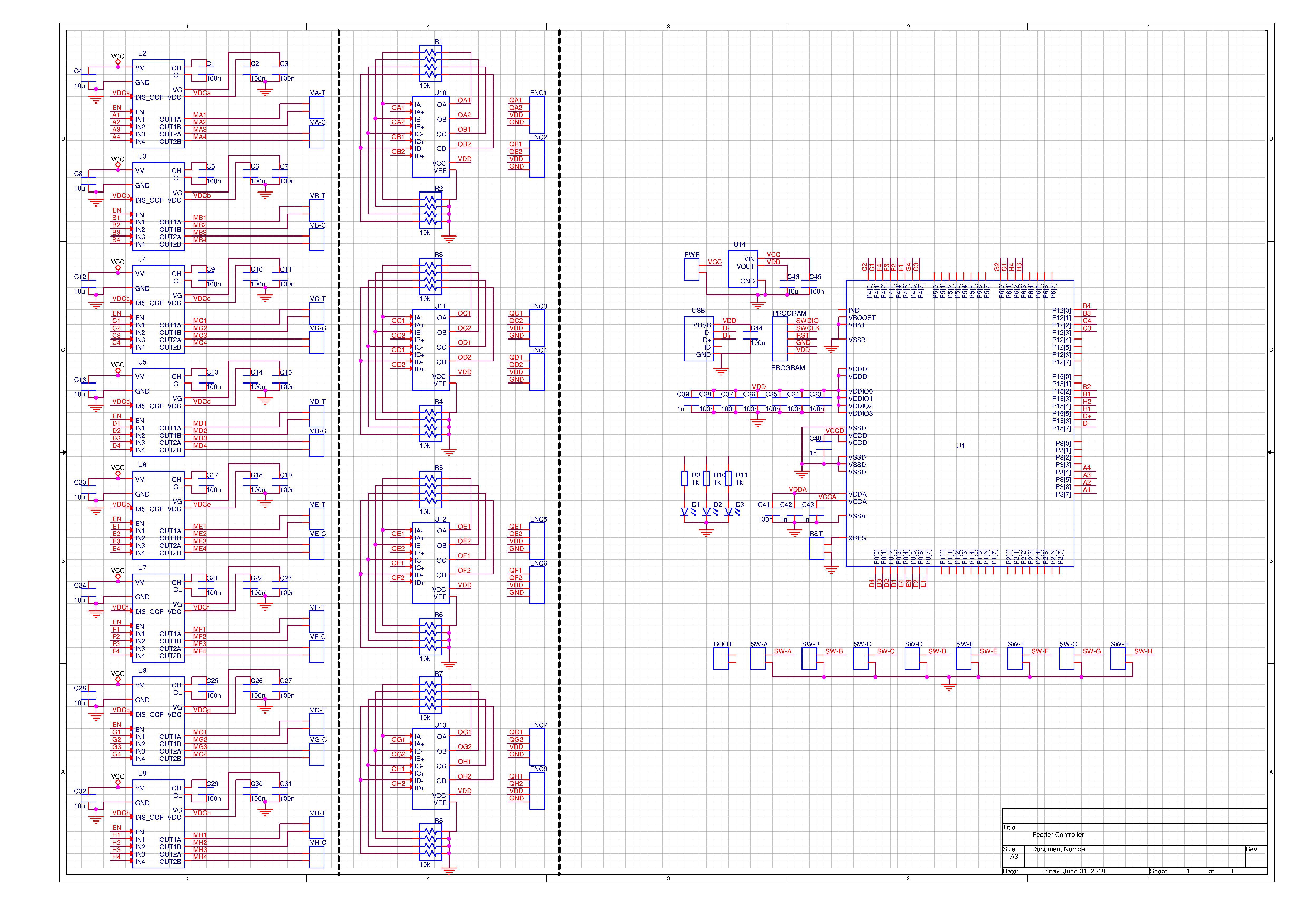
You can get a PDF copy of the schematic via Github (https://github.com/ottoragam/Kinnow). There you can also get the STL models of the feeder parts.
The board is going to support 8 automatic feeders. I chose a PSoC5200 microcontroller. It is a Cortex ME3 unit with integrated programmable logic. The programmable logic is crucial to perform the quadrature decoding of 8 optical encoders and to generate the 32 pwm signals needed to drive the 16 brushed motors. It will have a USB bootloader to make things easier for the final user.
I selected the AP1010AEN motor driver for it's compactness and low cost. It is a dual H-bridge chip capable of driving motors up to 18V and 350 mA when using both channles.
There will be four 4-channel LM324 opamps to amplify the signal coming from the phototransistos used in the quadrature encoder sensors.
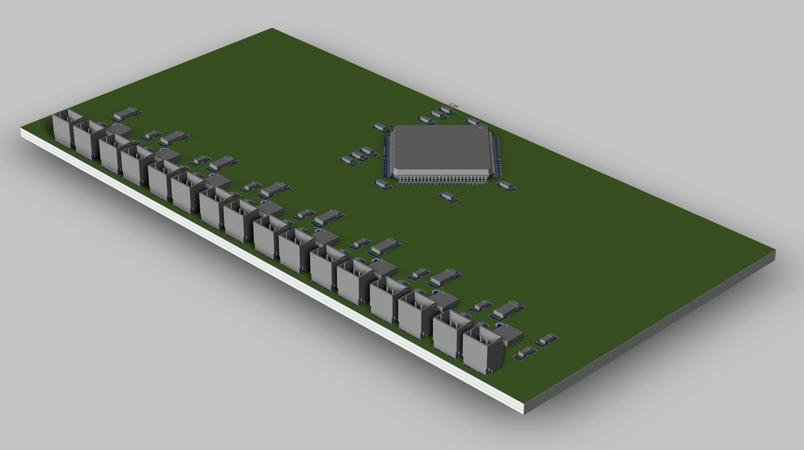
The boad measures 50x100 mm and it uses JST-SH connectors (1 mm pitch) in order to fit everything in a reasonable space. The controller is intended to work with a 6 to 12 V power supply, and it features an onboard voltage regulator for the logic, allowing for single supply operation.
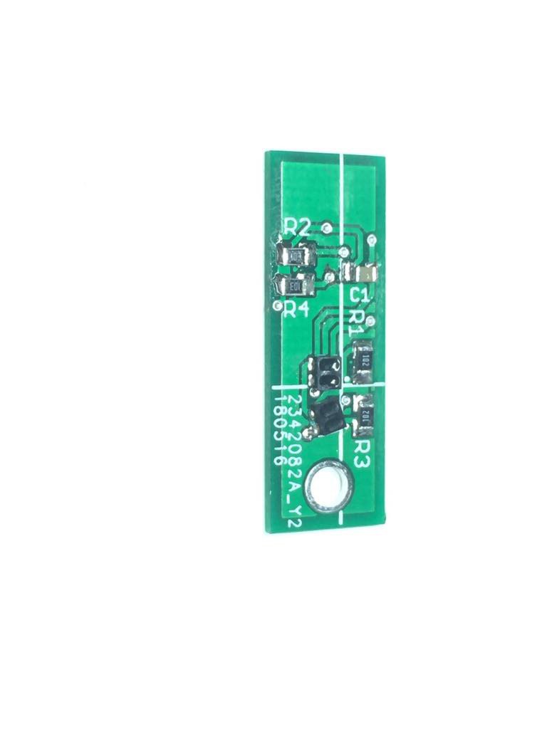
Also, last week I got the boards for the quadrature encoder sensor. I'm currently performing some test, and I'll publish the respective findings once I get a reliable quadrature signal.
Discussions
Become a Hackaday.io Member
Create an account to leave a comment. Already have an account? Log In.