I got the PCBs in the mail this week and soldered one up using the reflow skillet method. So far, it is mostly working. The main issue that I have come across so far is that the power enable signal, which is pulled up to 5 V, has its gate a few hundred millivolts too low when it should be high, so the PFET that it is controlling does not turn off.
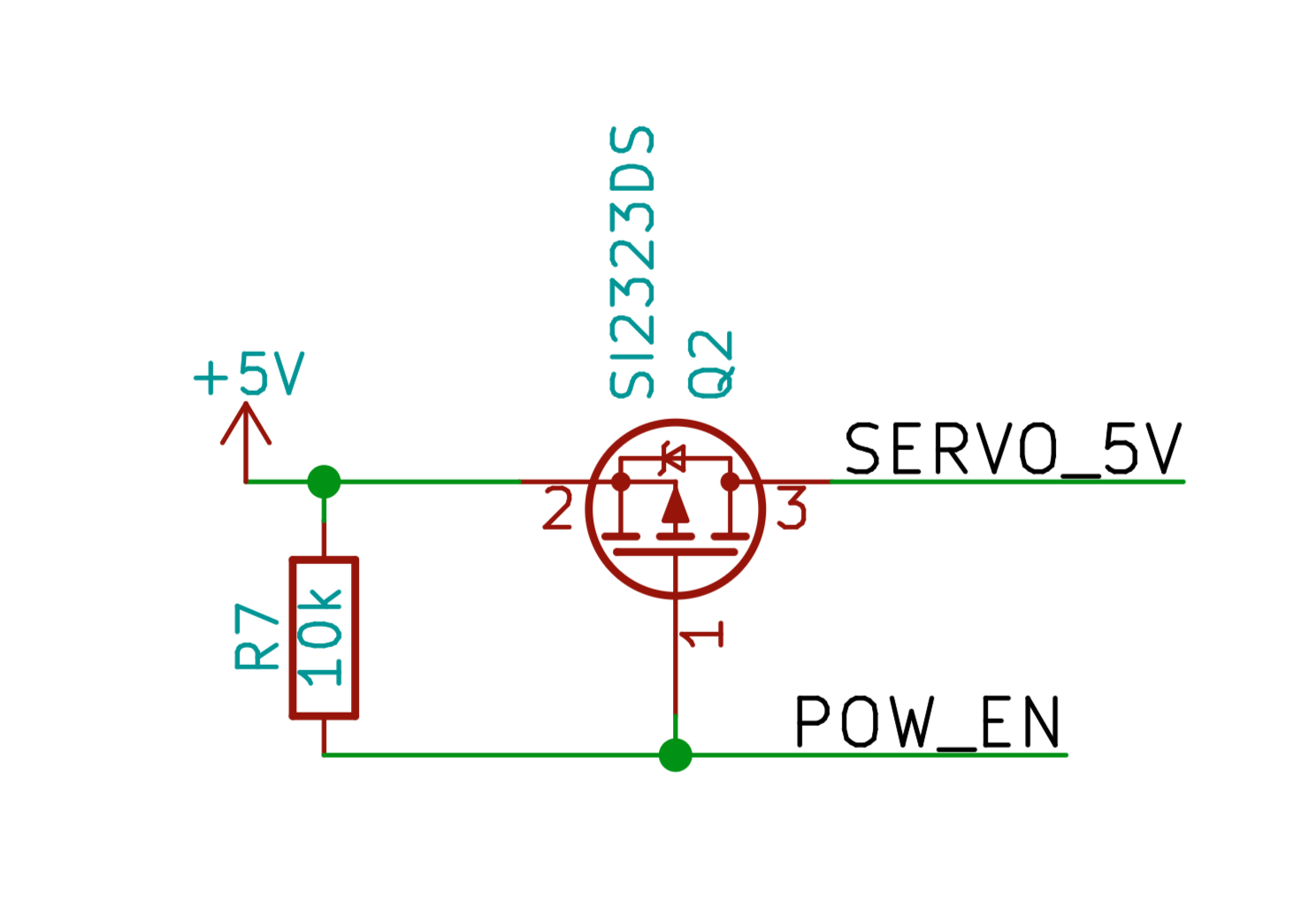
I am using pin PA4 on the STM32L476 in open drain mode to control it. I thought that this should work, but unfortunately this pin is not a 5 V tolerant pin. Looking at the datasheet, there are protection diodes on the pin that I believe are causing the issue. This means that the power enable signal unfortunately does not work on this revision of the PCB. It should be connected to a 5 V tolerant pin, also called a "TT" pin in the datasheet, such as PA2.
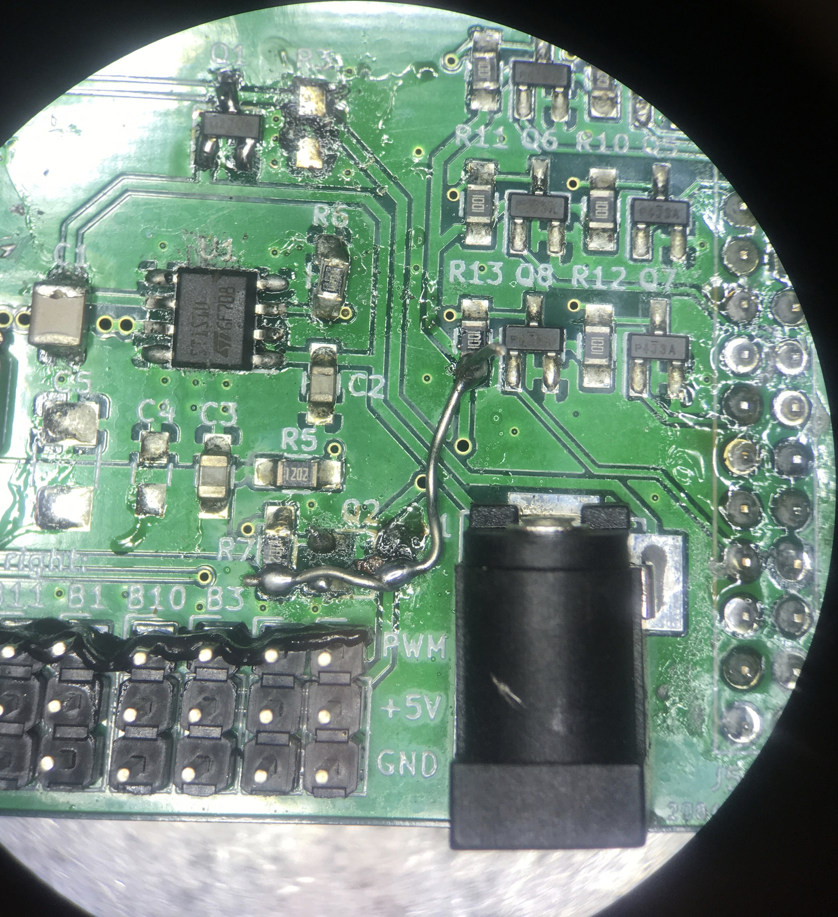
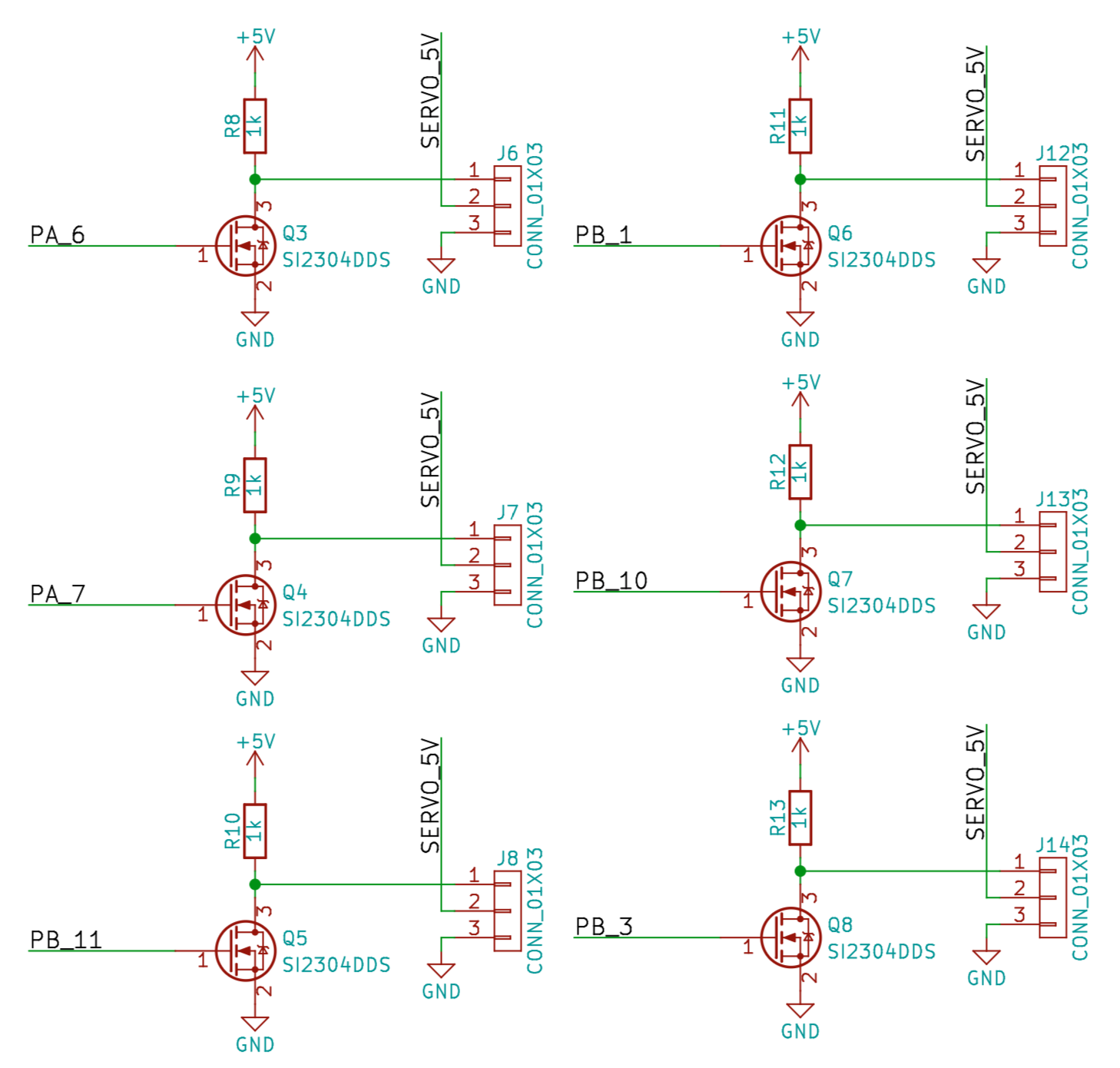
On a more positive note, the level-shifting circuitry is working. After debugging the above issue I had damaged the top copper layer so I did a messy soldering fix shown below to reconnect the 5V pull-ups. The NFETs convert 3.3V PWM from the micro controller to 5V for the servos. Note that since the FETs are inverting the duty cycle of the PWM signal also needs to be inverted. I was successfully able to move a servo motor, and have started putting together some firmware using the online Mbed compiler. The project is here.
Lastly, I also checked the Nunchuck interface. Unfortunately, the connector is slightly too narrow, so I had to sand it down a bit. But I2C communication worked great using the WiiNunchuck library on Mbed.
Discussions
Become a Hackaday.io Member
Create an account to leave a comment. Already have an account? Log In.