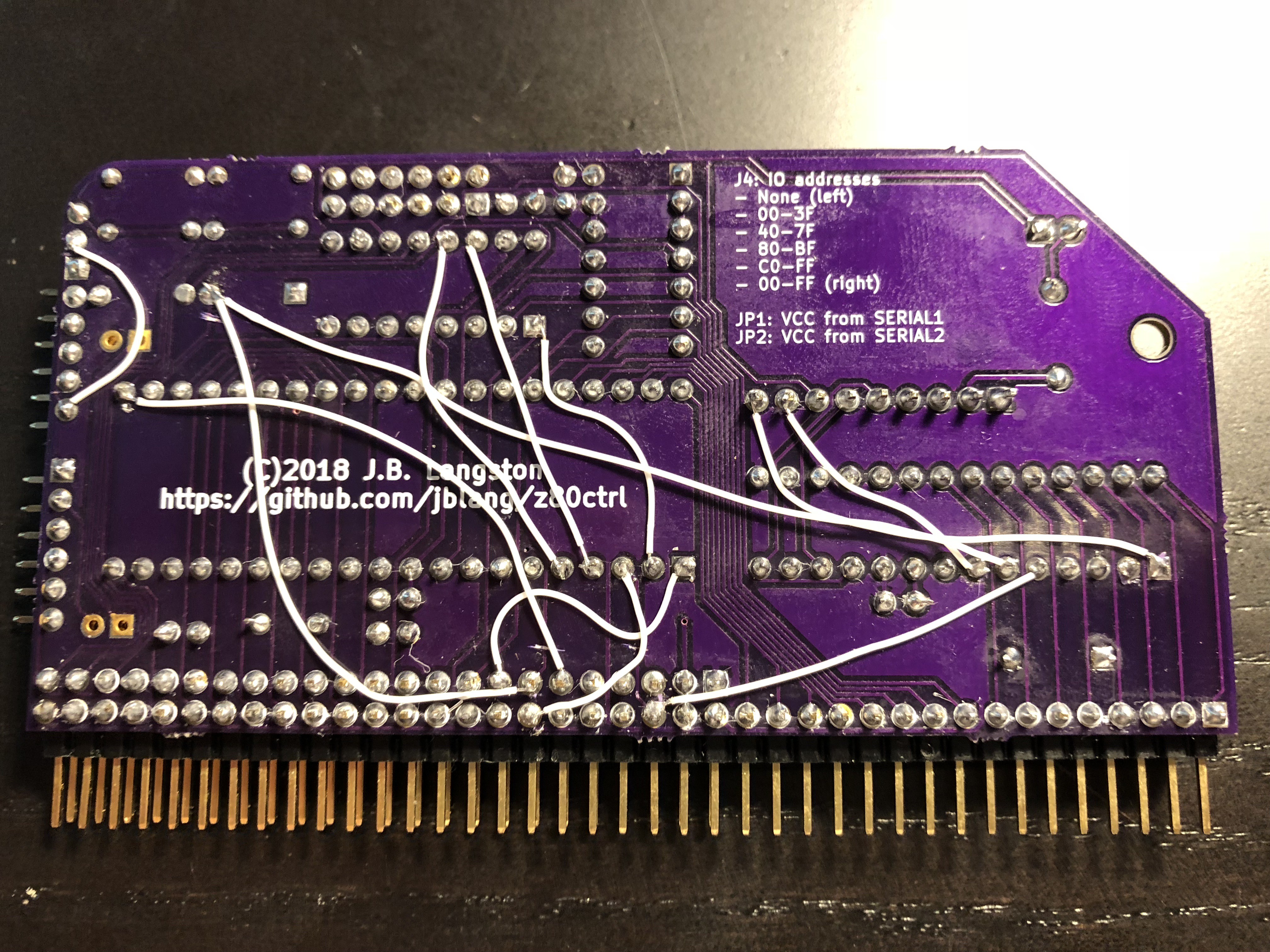
Even though REV2 barely saw the light of day (only one person I'm aware of had it manufactured), I am preparing REV3. The picture above shows the bodge wires on my REV1 board, which has been modified to implement the changes slated for REV3. These changes were necessary due to some issues found with previous revisions.
BUSRQ Optimization
First, although using BUSRQ instead of manually clocking when handing the data bus back to the Z80 solved the clock jitter that interfered with the sound card, it introduced a pretty serious performance regression. Non-DMA disk IO was over twice as slow as it was using the manual clocking method. It took about 6 seconds to load the game Ladder before, and 13 seconds after. I thought it seemed slower but only after rewatching the video I made demonstrating the software did I realize how bad it was.
This regression stems from the fact that BUSRQ is located on the IO expander, so toggling it twice for every single-byte IORQ introduced a lot of additional latency (about 4.8 microseconds per IORQ if I calculated it correctly). To fix this, I have moved BUSRQ to the local AVR PORTB, replacing the IOACK signal. Since BUSRQ has to be asserted any way to hand control back to the Z80, it can be connected directly to the reset line on the flip-flop to deassert the WAIT line. This saves a pin on the AVR and a few instructions in the code.
Other Pin Changes
I also decided that some of the other tradeoffs I originally made when assigning pins to the AVR or the I/O expander were not optimal. MREQ and BUSACK are used during DMA transfers, and now that DMA is used to service disk IO requests, having them on the I/O expander makes the transfers slower than they need to be. M1 is only needed during debugging and interrupt response, which are both slow anyway because the other signals they use are already on the IO expander, so it seemed like a good tradeoff. HALT only needs to be sampled periodically and is not highly latency sensitive so it can be moved to the I/O expander. Therefore, these signals have been swapped between the AVR and I/O expander: HALT for BUSACK, and MREQ for M1.
Fixed SPI Address
The initial board design had SPIA0 and SPIA1 signals crossed between the AVR and the 74HCT139. This caused the SPI addresses 1 and 2 to be backwards. This was fixed in software, but in REV3 I have fixed it in hardware so that the SPI addresses are now in the intended order.
Two-Way IORQ
Second, because the way I set up the IO address decoding, it was not possible to use IORQ as an output to control other peripherals directly unless the jumper was set to address all IO ports (00-FF), which connects the IORQ pin directly to the IORQ bus line. If the jumper were set to any of the 4 subsets of IO ports, which come from the 2-to-4 decoder, or to address no IO ports, which ties the IORQ pin directly to VCC, setting the IORQ pin to an output would cause short circuit and potentially damage both the decoder and/or the AVR.
I fixed this by directly connecting the IORQ pin on the AVR directly to the bus and using the jumper to select only the IORQ signal that goes to the flip-flop. Therefore, it's still possible to select a subrange of IO ports to trigger wait states for, but the AVR won't burn itself out if you do. This has the downside that it's now necessary to configure the IO port range that the AVR responds to in software to match those configured by the jumper, since otherwise, the AVR will attempt to respond to IORQs for which the flip flop will not trigger a wait state. This will lead to strange behavior any time the Z80 attempts to access one of these IO ports.
SD Reset
Next, I had identified an issue where the SD card would get into an inoperable state if the power to the RC2014 were turned off but the USB to serial adapter were left connected. This is because the USB-to-serial adapter provides enough leakage current through the RX and TX lines to keep the SD card at least partially powered so that it doesn't get reset properly. As the SD card has no separate reset line, the only way to reset it is to remove power.
Fortunately, the SD adapter from Pololu has an EN pin which can be brought low to disable the 3V regulator and cut power to the card. I have now connected this pin to the IO expander, so that it is now possible to reset the SD card from software.
Adafruit SD Header
I've also added an additional header to the board to allow using the Adafruit SD Breakout in addition to the Pololu Breakout that was previously used. I didn't feel comfortable relying on a single vendor for my SD Breakout, and the Adafruit board has the advantage that it is carried by Digi-Key and Mouser, allowing the entire BOM to be ordered in one place.
Unfortunately, the Adafruit board does not have an EN pin to cut power to the SD card, thus it is not able to be reset automatically. This is not a huge deal, as the card can be reset by temporarily ejecting and reinserting it or by unplugging the USB adapter, but it is a nice feature to have, so I still prefer the Pololu breakout. However, this will give people building my board another option.
ISP Header Moved
Finally, the only person to build a REV2 board let me know that the AVR ISP header I added is too close to the IO expander socket and the resistor for the SD activity LED when using a shrouded cover. I have nudged it a few mm up and to the left to hopefully give enough clearance for this.
Conclusion
To summarize the pin changes:
- Pin 1 on U4 changed from SDCD to SDEN
- Pin 5 on U4 changed from BUSACK to M1
- Pin 6 on U4 changed from MREQ to HALT
- Pin 7 on U4 changed from BUSRQ to SDCD
- Pin 1 on U2 connected to BUSRQ in addition to IOACK
- Pin 2 on U2 connected directly to IORQ bus instead of jumper
- Pin 3 on U2 changed from M1 to MREQ
- Pin 21 on U2 changed from HALT to BUSACK
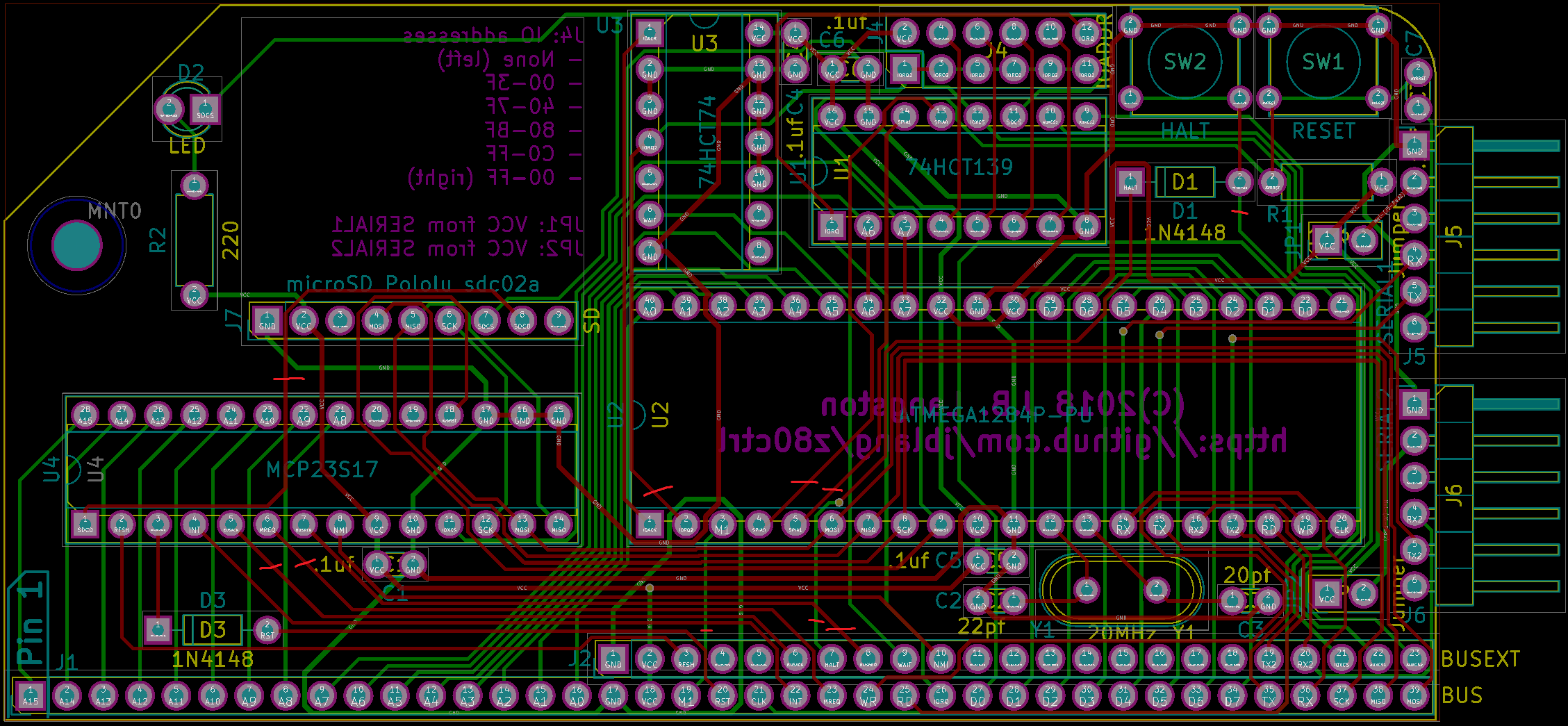
If you want to make these modifications to your REV1 or REV2 board as well, you can use the above picture of the bodge wires as a guide. Be sure to also cut the existing traces with an Xacto knife or you will short things out. The red marks on the image below indicate the traces that should be cut.

Make sure you flash the firmware for the correct board REV before you plug the modified z80ctrl and a Z80 board into the same bus. Otherwise, you risk shorting out the M1 and BUSRQ signals. You must also edit your Makefile and set BOARD_REV=3.
The REV3 boards have now been successfully manufactured and tested, so if you don't want to bother making these modifications to your old REV1 or REV2 board, you can have the latest REV3 manufactured instead.
 J.B. Langston
Discussions
Become a Hackaday.io Member
Create an account to leave a comment. Already have an account? Log In.