 Dan Maloney
I guess my first job is to define what duty cycles relate to which processes. There's an abbreviated chart in the user manual, but the label on top of the welder seems to have much more information:
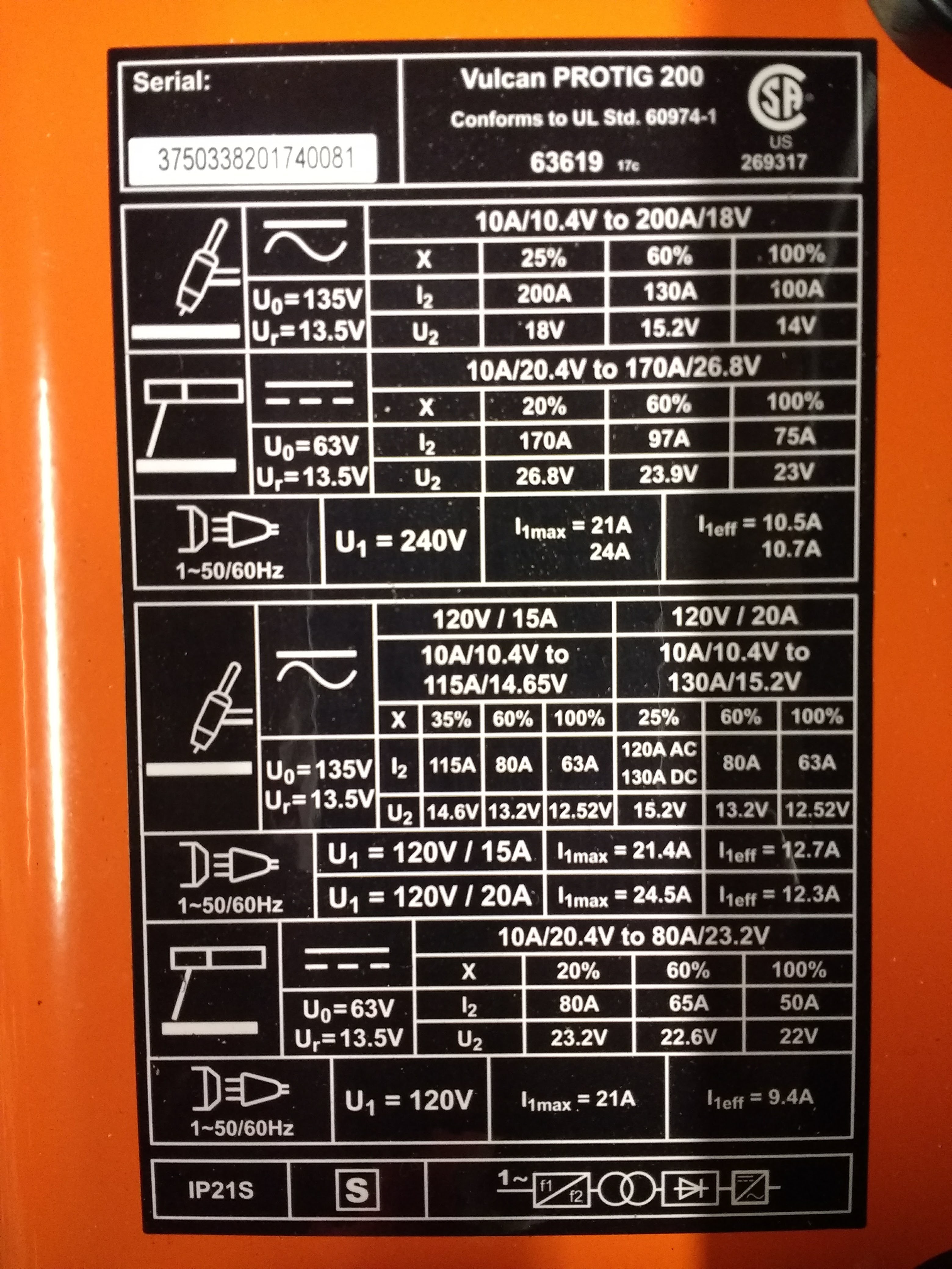
My hieroglyphic is a bit rusty, but what I think I'm gleaning from this is:
| Process | Supply | Min Duty Cycle @ amps | Max Duty Cycle @ amps |
|---|---|---|---|
| TIG | 120V | 35% @ 115A | 100% @ 63A |
| TIG | 240V | 25% @ 200A | 100% @ 100A |
| Stick | 120V | 20% @ 80A | 100% @ 50A |
| Stick | 240V | 20% @ 170A | 100% @ 75A |
There doesn't seem to be any differentiation between DC and AC TIG, which is good. I'm going to assume that the relationship between amps and duty cycle is linear, so I can extrapolate duty cycle for an arbitrary amperage setting from the slope of the line between the min and the max values and setting a hard limit on the minimum values.
But, this also means I have to take into account not only which process is being used and the amperage setting, but somehow I need to detect the supply voltage as well. That could be tricky. I've also got to decide how I'm going to keep track of things when I change the amperage setting while a duty cycle countdown is in progress.
Something to noodle. I guess I should probably look inside this thing soon, to see what treasures lie beneath that fetching orange skin.
Discussions
Become a Hackaday.io Member
Create an account to leave a comment. Already have an account? Log In.