Close
0%
0%

STM8 eForth Wireless Sensor

Just because everyone else is doing it with C doesn't make it right ;-)

Similar projects worth following
The goal of this project is building a low cost sensor network with STM8 eForth, STM8L, and low cost "nRF24L01+ compatible" transceiver modules. KiCad was used for designing PCBs.

The whole thing started with possums, but you'll have to ask @richard about that. In any case, it gave me the opportunity to look for that box full of nRF24L01+ modules in the basement, and start hacking with Richard on an nRF24L01 library for STM8 eForth. I also revived a habit of making PCBs, that I broke 25 years ago. However, I promised my wife that I won't need Fe(III)Cl3 this time. @oshpark & Co make keeping this promise easy, and learning KiCad was a matter of two weekends.

  • STM8L vs STM8S Interrupts

    Thomas06/25/2018 at 05:46 0 comments

    The STM8S external interrupt configuration is very limited (one interrupt vector per port A through E). As long as just one GPIO triggers the interrupt one knows implicitly what caused it. When more than one input is used it's not so easy.

    The STM8L applies this scheme only to the ports B and D. A second set of interrupt vectors capture interrupts triggered by port inputs Px0 through Px7 for ports A through E (plus port F in the case of PF0). It's thus possible to get two interrupts for the same port B or port D change, or (which is more useful) to have two different interrupts for, say, PB2 and PC2.

    The STM8L family has more options than in the STM8S family but still one has to be very careful when designing a circuit.

  • OSHPark PCBs quite simply look great

    Thomas06/14/2018 at 04:14 0 comments

    About 3 weeks after transmitting the KiCad gerber files 3 PCBs arrived from the USA. To my surprise the finish is ENIG (gold) not HASL or similar, which looks great. This makes the price of my small prototyping batch even more surprising!

    The soldering mask of the KiCad TSSOP footprint, and very accurate rendering, made soldering the µC easier than thought, certainly easier than any cheap "TSSOP20 DIL adapter PCB" I soldered so far.

    Of course I made a mistake with the PCB, but it's a minor one: the drills for the CR2032 battery holder are a bit too small. Half a minute with a nailfile made the pins fit in. No problem, but I'll update the PCBs. Otherwise the components all sit at the right spot.

    In the meantime, the nRF24 code has been refactored and made ready for using STM8L051 instead of STM8S103 (or for any other STM8 eForth target). Hopefully I'll get to implementing the Ping application soon :-)

  • Step1: STM8L051F3P6 breakout with nRF24L01+

    Thomas05/19/2018 at 07:55 2 comments

    This HaD project begins with my latest STM8 eForth log.

    Richard's nRF24L01 library for STM8 eForth was a very good starting point for experimenting with the most prolific of all transceiver devices (in the meantime I learned that genuine nRF24L01+ chips are rare, and the best one can hope for is the "quite OK" SI24R1. For simplicity I'll refer to it as nRF24L01, and I also try to get a set of radio modules with genuine chips to test compatibility.

    The cool thing about using STM8 eForth is that it's far more than a programming language on a nimble µC: it's also an operating system and a programming environment. I'd like to explore how to install features, "software apps", over the air.

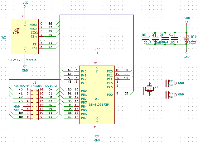
    For obvious reasons, a wireless sensor should consume very little energy, and selecting a µC with an RTC and very low energy needs in halt state is an important requirement. I'll start with cheap CR2032 coin cells, but other power supplies will be considered (e.g. a "solar garden light" style power supply with a single NiMH cell). I designed a STM8L051F3P6 breakout board that will be the foundation for my first experiments. As a PCB design tool I use  KiCad 5.0.0.rc2, and the first set of PCBs I ordered it from @oshpark.

    While I wait for the PCBs to arrive, I'll be working with an STM8L051F3P6 breakout I made some time ago, and I'll try to design a first sensor PCB with a humidity/temperature sensor.

    @Wassim uses a BME280 chip in his Home Smart Mesh project. The page Humitidy Sensor Shootout offers a great overview, and the Bosch chip appears to be one of the best. It also offers a barometric pressure sensor, let's see what can do be done with it.

View all 3 project logs

Enjoy this project?

Share

Discussions

Similar Projects

Does this project spark your interest?

Become a member to follow this project and never miss any updates