Now that the sensors are mounted on a real robot we can get some measurements and check if the data is useful.
Thanks to the previous software work and the integration in ROS testing the sensors with a real robot is pretty straightforward. Changing the wheel_radius and wheel_separation parameters in the file to launch the differential odometry computation software is all we need. Adapt the system to different platforms is fast and easy :)
After checking that everything was up and running we were ready to record some datasets to work with the data offline. We made some tests and here you can see the result.
Linear trajectory

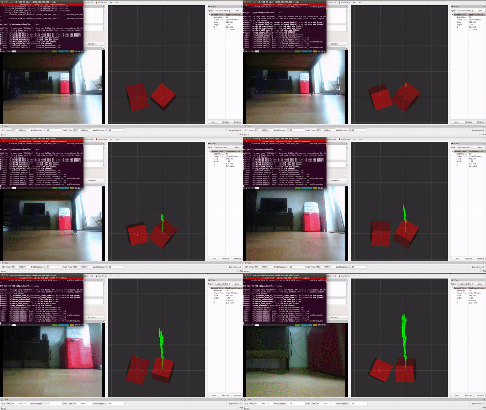
As it can be seen in the left side of the upper animation, the displayed image is the recorded video with the robot camera, the red boxes are the output of the IMcoders (one per wheel) and the green arrows are the computed odometry from the algorithm we developed (btw, thanks to Victor and Stefan for the help with it!).
Here it is the same dataset but this time displaying just the computed path followed by the robot (red line):
Left turn trajectory
Complex trajectory
In this video you can see an additional yellow line which is also displaying the path followed by the robot but with a different filter processing the output of the IMcoders. Probably you noticed that the trajectories are slightly different. This is because several algorithms can be used to compute the pose of the robot wheel.
Due to the time constraints we had no time to prepare a proper verification environment so we cannot ensure which one is better.
Conclusions
Finally, we can conclude that much more time shall be invested in the research of algorithms for computing the estimated orientation of the wheel due to the important role that they play when computing an odometry out of it.
 Alfonso Troya
Discussions
Become a Hackaday.io Member
Create an account to leave a comment. Already have an account? Log In.