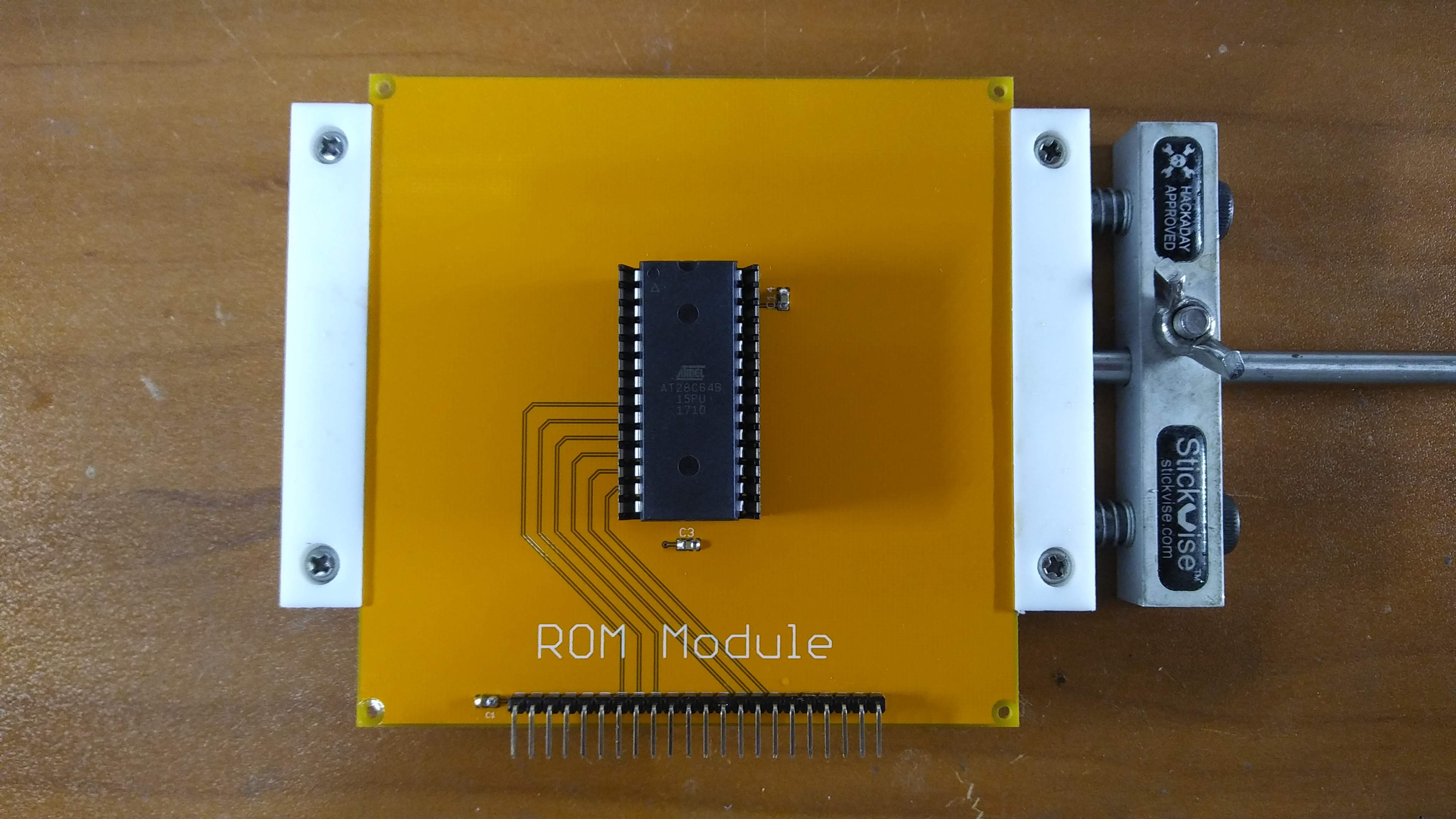
So all of the PCBs arrived yesterday, and all of the remaining parts arrived today.... time to begin assembly. When I started looking at the boards this evening, my original intention was to assemble the boards in a strict order with a log post for each, however, I succumbed to temptation and started with the simplest board: The ROM Module. The ROM Module only consists of three capacitors, the i/o header, and the ROM, so it was the lowest hanging fruit of the design. My intention was to populate the board with a standard socket, and then use a Zero Insertion Force (ZIF) socket on top of that, but after visiting my local surplus shop Tanner Electronics, I discovered they had some inexpensive Low Insertion Force (LIF) sockets. The price was right and they seemed to do the job, so I purchased 10 pieces. I will also be using these LIF sockets on the Decode Module. I've selected the Atmel AT28C64B-15SU EEPROM to use in this project. It's an 8k x 8 device, supported by most of the inexpensive eeprom programmers like the TL866 series which we will discuss in a later log post. In addition, they are relatively inexpensive, and available in quantity from retailers like Digikey and Mouser. One down... seven to go..
 Dave's Dev Lab
Discussions
Become a Hackaday.io Member
Create an account to leave a comment. Already have an account? Log In.