Moving the Unused Bit
Here are the changes I made to move the unused bit to the least significant end.
- The carry-in logic and initialisation of the Zero FF now takes place at T1 of an LSW instead of T0.
- The logic for extending bit 16 to bit 17 of an MSW has been removed, and the sign is captured in the Sign FF during T17 instead of T16.
- The Z ouput of the ALU is now forced to zero during T0 of an LSW.
- Inputs to the Instruction Register are taken from outputs Q2-18 of the S Register (where Q18 is the same as the serial input).
- Shift Left and Shift Right instructions are now terminated when bit 1 of the S Register is 1 instead of bit 0.
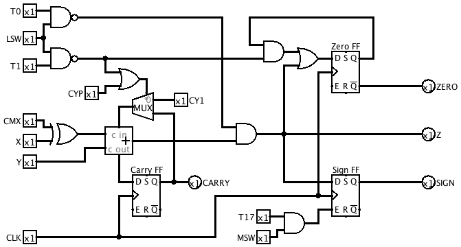
This is the revised ALU subcircuit:
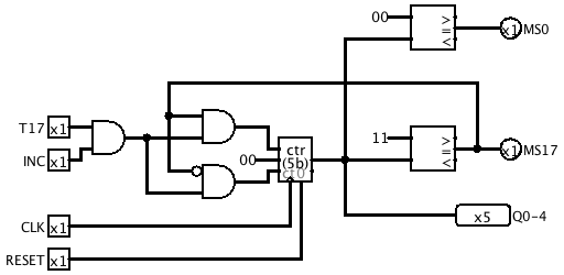
Multiplication Step Counter
We need a way to tell when we've carried out the required number of shift-and-add cycles when multiplying. The Multiplication Step Counter (MSC) does this. It counts up to 17 and then wraps back to 0 ready for another multiplication. A new control signal INCMS enables incrementing the MSC, and a new microcode branch condition (number 2) tests whether the MSC has reached 17.
Multiplication Flowchart
Here's a flowchart showing the general strategy for implementing the Multiply and Add (V) instruction.
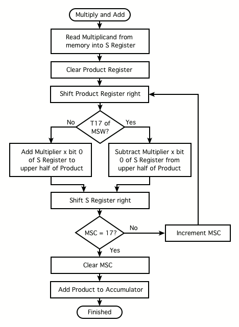
We can combine some of the operations that are shown as separate steps in the above flowchart. Not only will this save time, it will be necesessary if we want to stay within our 15-microinstruction budget for the long-word versions of the multiplication instructions.
Other changes to support multiplication
I changed the register file addressing so that the output of the Register Address Incrementer goes only to the Accumulator and Product Register, with the Multiplier Register receiving the unmodified register address. Activating RSH while adding the multiplier to the product then causes bit i+1 of the product to be added to bit i of the multiplier and written back to bit i of the product, thereby performing Product <-- (Product >> 1) + Multiplier.
An AND gate computes the product of the Multiplier with bit 0 of the S Register, and this is made available as an X input to the ALU.
The Product is made available as a Y input through a gate that forces it to zero during the first multiplication step. This allows clearing the Product to be overlapped with the first multiplication step.
The Product is also available as an X input, so that it can be either added to or subtracted from the Accumulator at the end of a Multiply and Add or Multiply and Subtract. The XSEL field had to be widened to 3 bits to allow for this.
I added two control signals MLSW and MMSW to indicate when the least or most significant words of a multiplicand are being processed. To save microinstruction bits, these have been combined with RSH and HALT in a decoded field called MISC:
001 MMSW
010 MLSW
011 RSH
100 HALT
Logic has been added to the ALU to perform subtraction during the last bit period of a multiplication if the MSB of the multiplicand is set.
Revised ALU ![]()
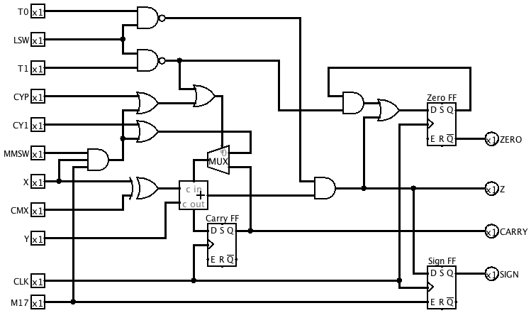
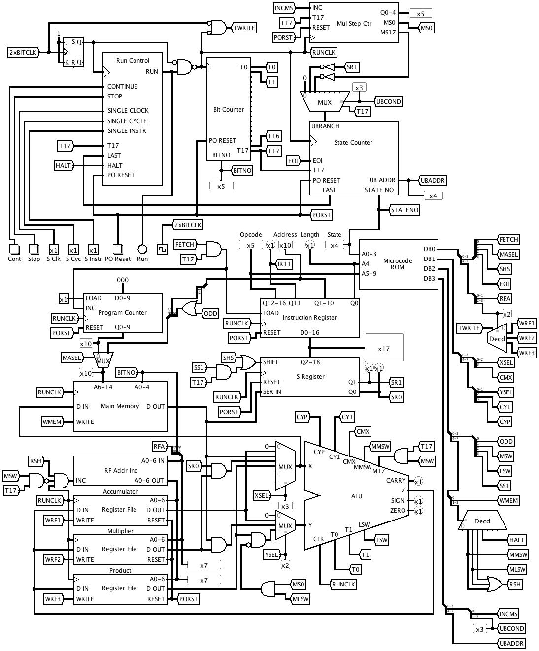
Revised Main Circuit
Discussions
Become a Hackaday.io Member
Create an account to leave a comment. Already have an account? Log In.