Close
0%
0%

Automagic Strike and Dip

A device to automate strike and dip measurements for geological mapping.

Similar projects worth following
The strike and dip of a rock outcropping is the angle that the rock slopes (dip), and the compass direction perpendicular to the direction that water would flow down the dip (strike). When creating a geological map many dozens or even hundreds of these measurements must be made. This is traditionally done with a transit compass which takes time, skill, and may introduce errors.

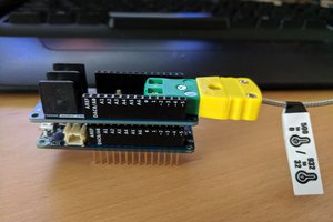
I wanted to make a device that would automate the process. What I've got is a board (I haven't yet made an enclosure for it) that you can put on the rock, push the button, and get the strike, dip, longitude, latitude, altitude and time all scribbled out to an SD card in CSV format. The prototype is built using an Adafruit Feather M0, but I'm in the process of designing a custom board and redoing the firmware using the standard STM32 HAL.

This is the project page for the prototype/proof of concept, using the Arduino IDE and breakout boards for testing.  I still need to take the little guy out and test it against a transit compass and a strike and dip phone app to see how it compares, and I'll be updating the project with the results as soon as they're completed and written up.

It uses the American right-hand rule for strike measurement.  The POC version does not have a means of setting the magnetic declination other than hard coding it, but the STM32 version will have extra buttons for that.

This project would have been really easy to put on a standard through-hole prototype board, but I wanted to have a board custom made because it made me giggle.  It turns out that I'd accidentally used the wrong Adafruit 9DOF in Fritzing, so that's why the two "noses" on the right side of the accelerometer are chopped off.  There's also a really ugly jumper soldered from the empty pin made from the shift to the right to the actual power pin on the 9DOF.

The repository for the prototype pictured here is at https://framagit.org/JakeSparkleChicken/StrikeDipC

The repository for the current project is at https://framagit.org/JakeSparkleChicken/strike_and_dip_stm32f7

StrikeAndDip_bb.png

Breadboard diagram

Portable Network Graphics (PNG) - 384.70 kB - 06/02/2018 at 19:23

Preview

  • 1 × Adafruit Feather M0 Adalogger
  • 1 × Adafruit OLED FeatherWing
  • 1 × Adafruit Ultimate GPS v3
  • 1 × MPL3115A2 I2C Barometric Pressure, Altitude, Temperature Sensor
  • 1 × Adafruit LSM9DS1 9DoF Breakout

View all 6 components

  • Major overhaul

    Jake Moomaw01/27/2019 at 23:01 0 comments

    I decided to try to put the WMM automatic magnetic declination algorithm in the unit, and the STM32F0 was too wimpy to handle it.  That being the case, I've moved it over to the STM32F746ZG to ensure that I've got enough oomph.  Once I've got it done I'll see about optimizing it for something a little smaller and cheaper.  I also swapped out the IMU for the BNO055 so I don't need to worry about integrating the accelerometer and the magnetometer anymore.  I'm working solely with the STM32 HAL at this point, and the repository has been moved to Framagit from GitHub.


    Currently the SSD1306 display and the BNO055 are working to full functionality.  GPS code is next on the list, but my school break is coming to an end and I'm not too sure when I'll be able to get to that and the SD card stuff.

  • Testing went poorly

    Jake Moomaw06/27/2018 at 19:58 0 comments

    I took the prototype out to a forest preserve by my apartment on Sunday to do a little field testing.  Since I live in the Chicago area and would have to go about 150 miles to find the nearest natural rock outcropping, I had to settle for man made structures.  The reason that is important is I'm not sure if those structures are just concrete or if they are steel reinforced.  This made Sunday's excursion a rather poor choice for actual testing of the unit.

    Regardless, the results were a bit on the abysmal side.  I tested it versus PocketTransit for Android and used an analog transit compass as a reference.  The dip measurement is spot on and matched what the compass was reading, while the phone app was typically 3° off.  Good news there!  Unfortunately, the phone app was on average 9° off on the strike versus 16° for the prototype.  One of the readings was a full 25° off from the compass!

    So one of four things is happening.  The structures may have had steel in them, the magnetometer may be too close to a highly active line which is causing magnetic interference, the fusion code is buggy as hell, or the magnetometer may be rubbish.  The next test will be to take out a wooden table with some books and cardboard to test and ensure that it really is a problem with the device instead of with the structures I was using.  After that, some tests with a magnet may be in order to more fully test the fusion code.  Lastly, if the fusion code checks out, I'll have to try using a different magnetometer which will necessitate a different board so that I can try moving it out further from the rest of the noise.

View all 2 project logs

Enjoy this project?

Share

Discussions

Similar Projects

Does this project spark your interest?

Become a member to follow this project and never miss any updates