Close
0%
0%

Smiley TOF Module

Compact TOF module for robotic applications

Similar projects worth following
899 views
The goal of this project is to make an easy to assemble, inexpensive TOF module for robotic applications using off the shelf components. This project uses an Adafruit Metro mini, a VL53L0X TOF sensor and a HiTec HS-311 servo motor. The enclosure was designed in CAD and 3D printed.

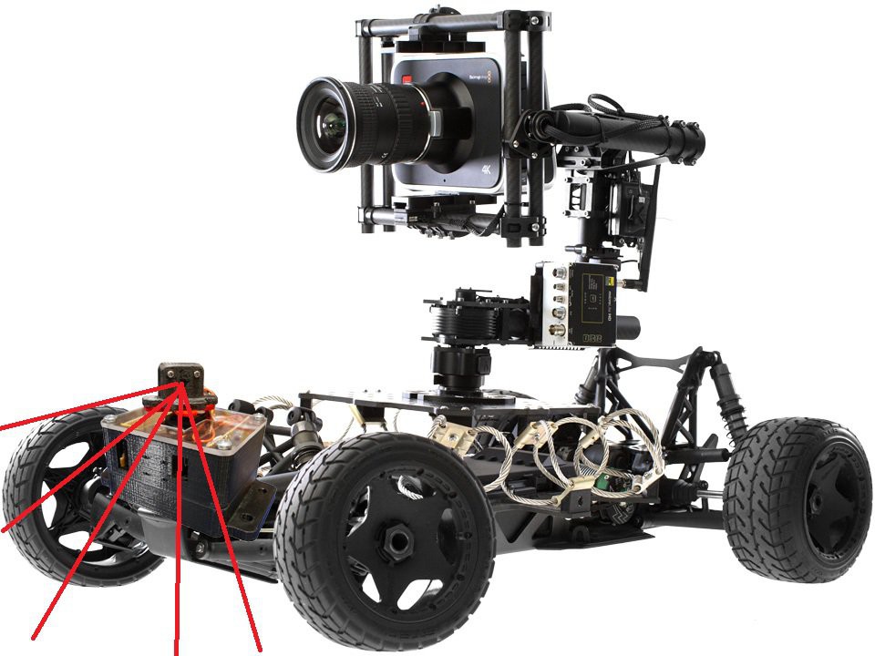
Time of Flight (TOF) sensors are quite useful in measuring distances between objects and a point of reference. Instead of measuring distances using an ultrasonic sensor, infrared proximity sensor or computer vision techniques, this tiny laser source and emitter based system measures distances based on the speed of light. These sensors are becoming more accurate, higher resolution and more affordable for use in the maker community. After a bit of searching, I did not come across a stand alone TOF sensor module for remote camera car operation. I decided to build my own dedicated TOF sensor unit that can be attached to a camera car with just (4) AA batteries and a few bolts. The goal is to produce a module that can be used alongside other sensory equipment to adequately analyze objects and rough terrain in the surrounding environment that would produce to great of an obstacle for the camera car suspension to dampen.

There are several all-in-one TOF laser-emitter packages on the market, such as the STMicroelectronics VL53L0X, VL53L1X and VL6180X, the Texas Instruments OPT3OPT8 and OPT9 Series, the Chirp Microsystems’ CH-101 and CH-201 and the Heptagon OLIVIA line of TOF sensors. I decided upon an STMicroelectronics VL53L0X unit because it seems to be the most commonly available TOF unit on the market.

To make this project as easily repeatable as possible, I decided to use parts that were as commonly available as possible. I took a tip to a microcenter and picked up the Adafruit metro micro, VL53L0X sensor unit and a HS-311 servo motor. The total BOM of this project is about $35. 

The ideal module for my application would look something like this:
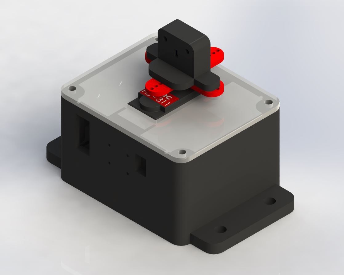
This is how I am imagining using the module. My photoshop skills are not the best, but there is limited space on the camera car for additional modules, as most of the body is designated for electro-mechanical dampening systems.
tof_device.ino

Arduino code for Metro Mini

ino - 1.77 kB - 06/04/2018 at 13:45

Download

base.STEP

Base for all the electronics

step - 354.00 kB - 06/03/2018 at 21:24

Download

batt_cap.STEP

Battery cap part of unit, with mounting flanges

step - 190.70 kB - 06/03/2018 at 21:24

Download

base.STL

Base for all the electronics

Standard Tesselated Geometry - 204.28 kB - 06/03/2018 at 21:24

Download

cover.STEP

Cover top plate for base

step - 60.31 kB - 06/03/2018 at 21:24

Download

View all 11 files

  • 1 × Adafruit Metro Mini Arduino Uno-like AtMega328 based microcontroller
  • 1 × VL53L0X Time Of Flight Sensor TOF sensor based on ST Micro VL53L0X TOF chip
  • 1 × HiTec HS-311 Standard servo motor 0-180 degree rotation
  • 1 × 4AA battery holder Standard AA battery holder
  • 2 × 0.1in pitch single row headers (male)

View all 9 components

  • 1
    The Design

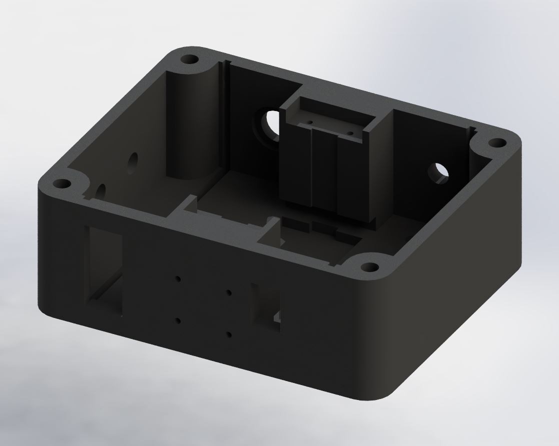
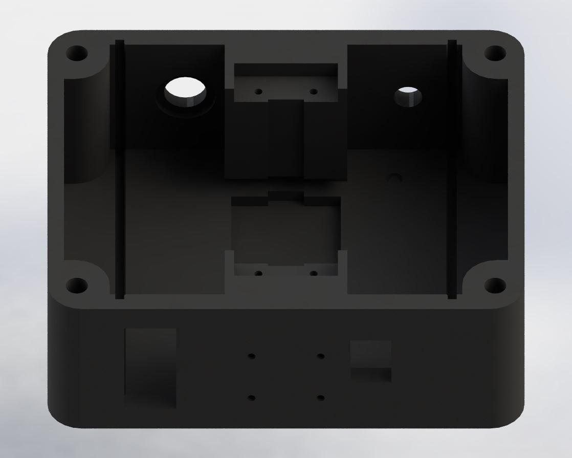
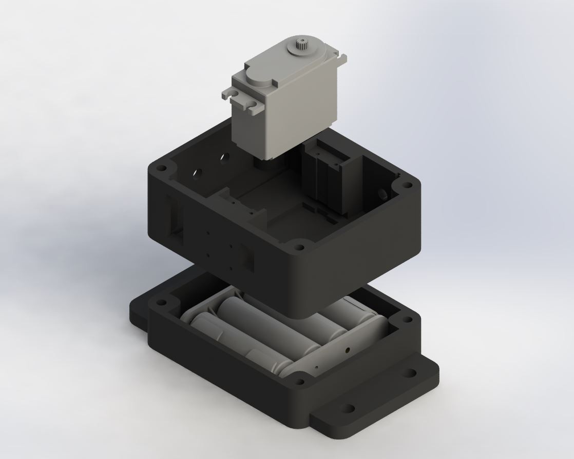
    After solidifying the design idea in my head, I began designing the enclosure for the sensor module. I decided to 3D Print the enclosure early on as I did not have any spare project boxes lying around and the servo motor is not project-box shape friendly. It features a T-shaped geometry that would require a custom mount, so 3D printing just made sense for this application. I wanted to keep the enclosure simple and volumetrically dense, yet still allow for easy servicing. Of course, I designed a rectangular box. It's no regular box though, and features a centered servo motor mount and PCB slots straddled around the motor.

    I added some panel mount holes for a toggle on/off switch, indicator LEDs, a DC jack and some face mount points. I decided on a traditional 4 hole through-hole bolt pattern to allow for additional modules to be bolted together in a sandwich like configuration.

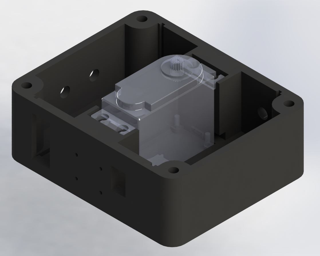
    Here's a better look at how the servo motor mounts inside the CADed project box. I could have located the motor on either side of the box, but I just ended up centering it for nicer aesthetics. 

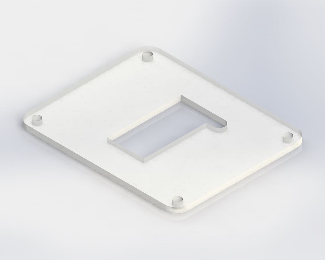
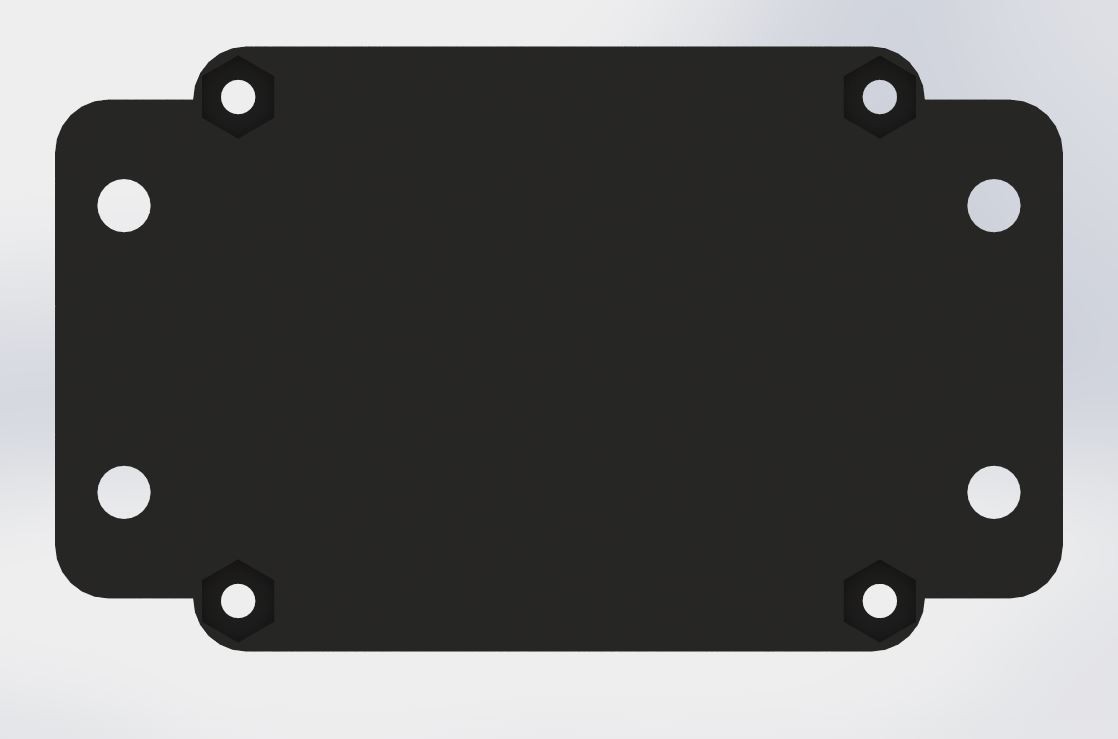
    Any good enclosure needs a lid. I kept it simple and designed a lid with four mounting holes, a cutout for the servo motor and a hole for the TOF sensor wireloom. Since this was a simple 1/8in thick sheet, I decided to just cut it out of plexiglass. I had a bunch of spare plexiglass scraps and plexiglass would add a whole other layer of cool to the project.

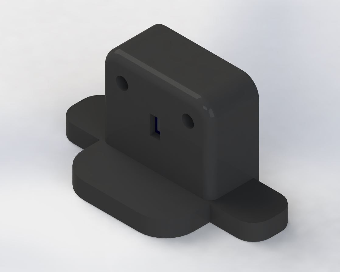
    The TOF sensor mount was more of a challenge to design. The sensor board has to be mounted co-linear to the axis of the servo shaft. There was an included plastic plus-shaped servo arm which aided in the mounting of the TOF sensor. I modeled a similar tri-wing base to align with the plug-shape design of the servo arm. 

    With a base established, I made sure to fully enclose the sensor board and leave a small square opening for the TOF sensor. This small slit acts as a lens hood and helps in the rejection of background noise and unwanted oblique reflections.

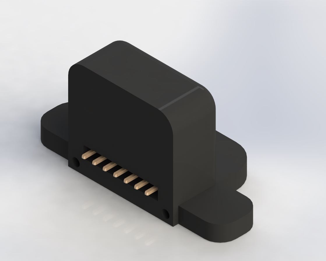
    I decided to reuse the 0.1in pitch header of the TOF board and just make a cutout around the connector. This way you could still reuse the sensor on other projects and you wouldn't have to buy a fancy connector. 0.1in pitch female connectors are perfect for this application because availability is extremely high and they are very inexpensive and reconfigurable. 

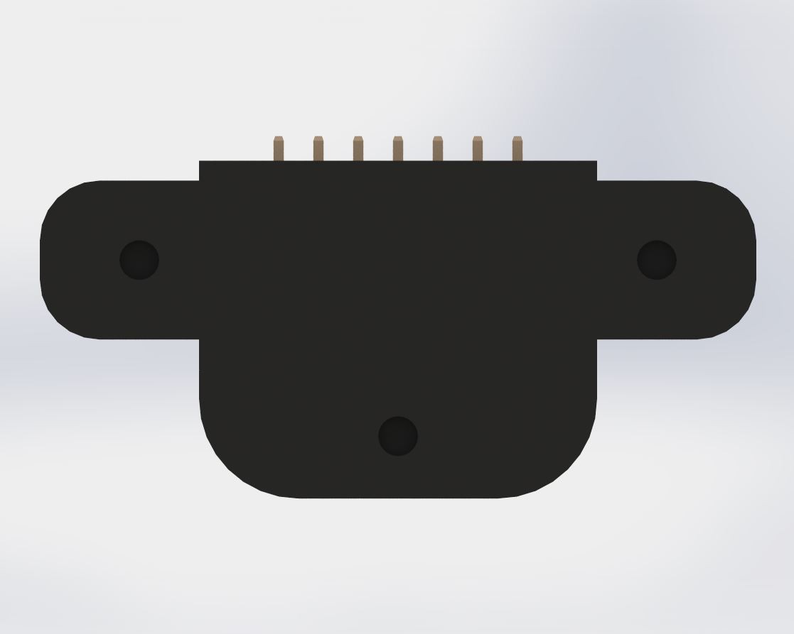
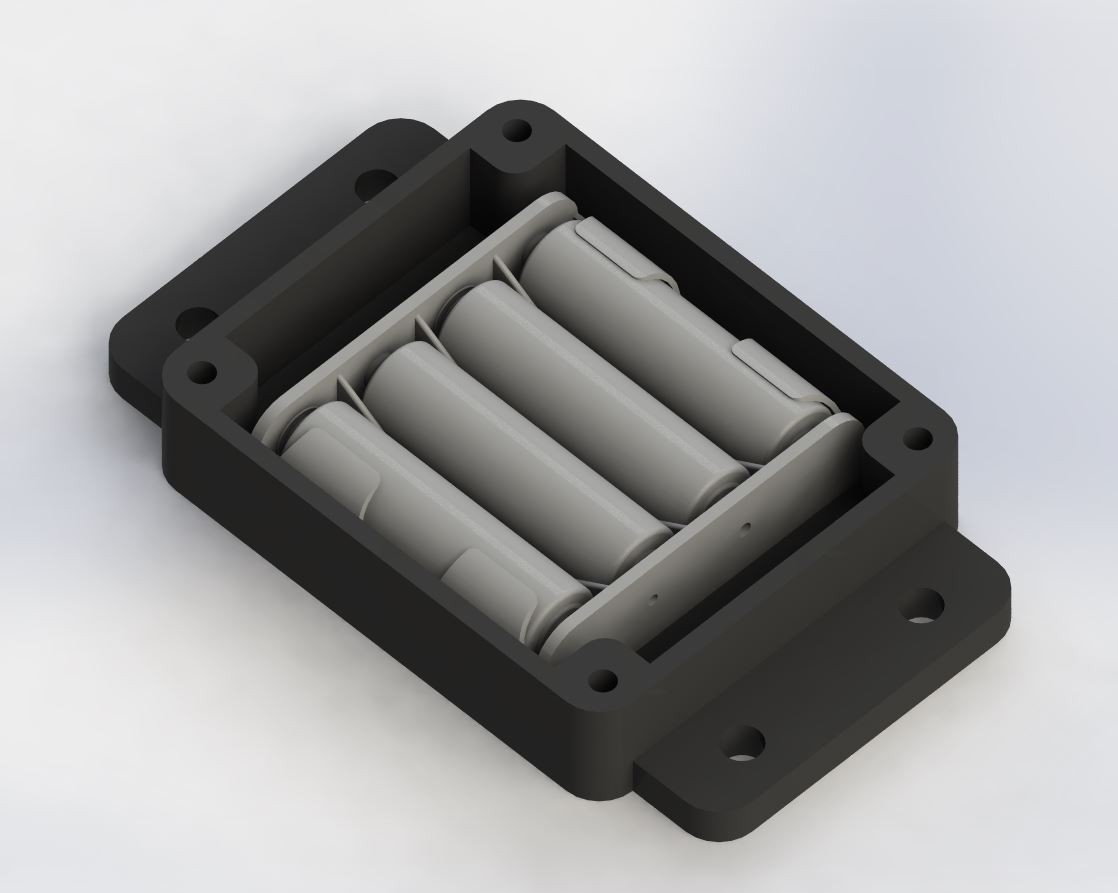
    The last unit is a modular battery cap. As you can imagine, this houses the batteries to drive the servo and arduino. It is designed to fit (4) standard SS batteries. The cap also has an integrated mounting flange to make an easy mounting experience.

    As an added bonus, the cap has (4) integrated nut holders, so the entire sandwiched assembly remains tightly packaged together as one unit.

  • 2
    The Actual Parts

    CADed parts are an ideal representation of the design you have in your head. CAD sets the bar. You just have to reach it. 3D printed parts usually come out a bit off and require a some modification if you are not generous with your design tolerances. 

    How I imagine the parts fitting
    How the parts actually fit

    It looks like I could have increased my tolerances by a few thousandths of an inch, but that's nothing a bit of sanding, filing and dremel-ing can't fix. 

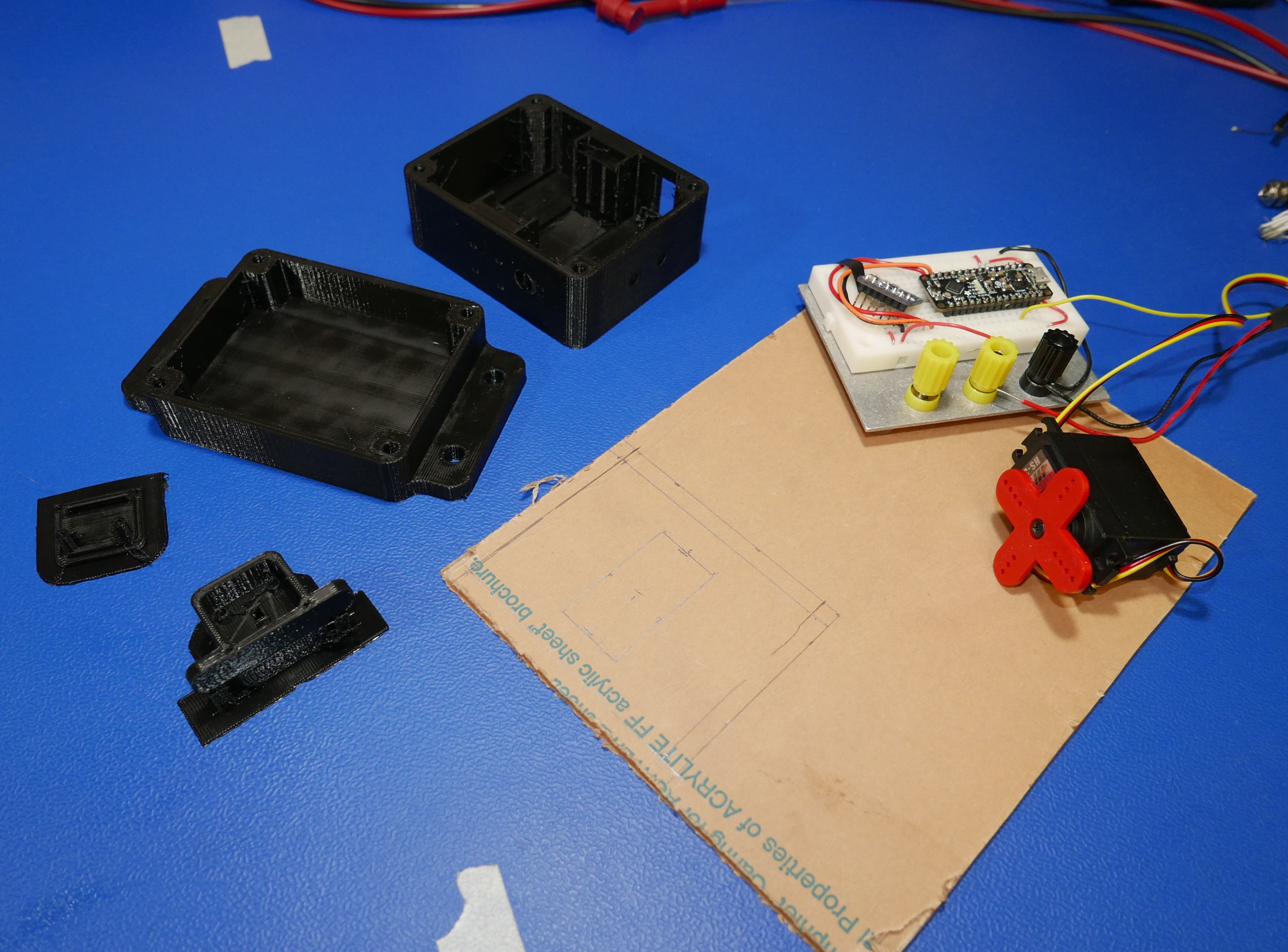
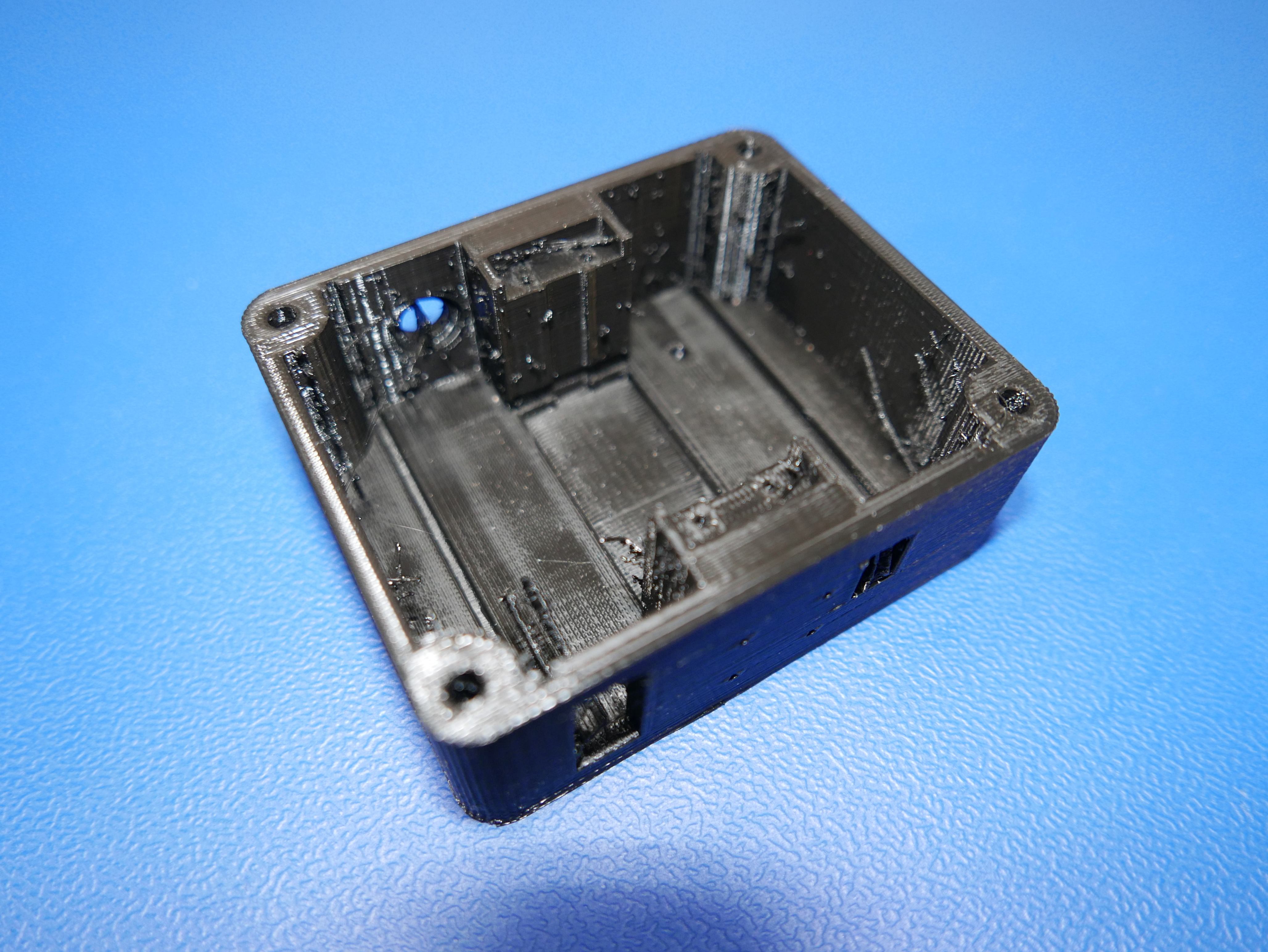
    Here's what the parts actually looked like:

    I decided to go with a medium fill on these ABS plastic parts. They didn't need to be incredibly rigid and I figured that I could benefit from a lighter weight assembly.

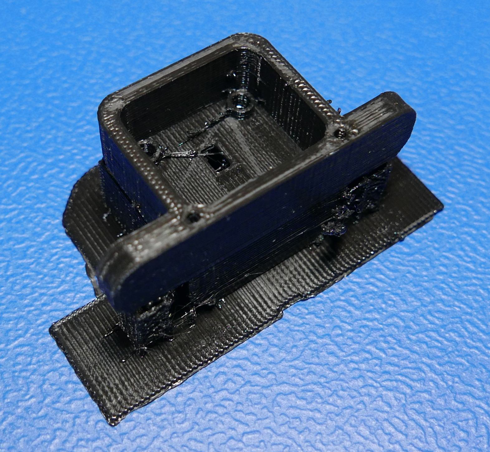
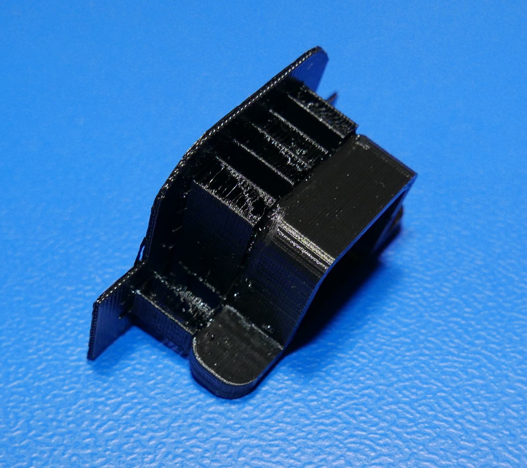
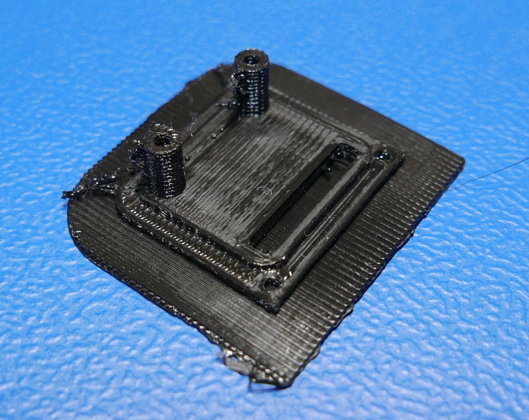
    As with any type of printing, there will be a cleanup phase. This is how the small parts looked right after prying them off the build plate.

    Back of the TOF sensor shell
    Side view of the TOF sensor shell
    TOF sensor mount

    The weird looking alien head in the previous picture says it all: "Please send help."

  • 3
    Testing & Fitting Phase

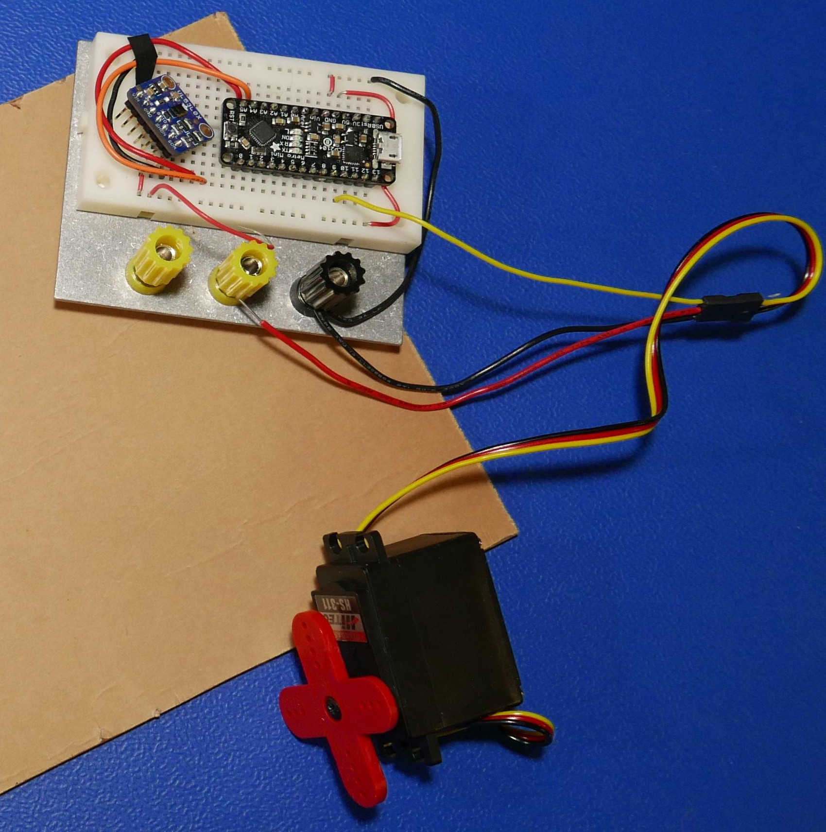
    It is always a good idea to test your design before final implementation. There is no better place to start than breadboarding! I took the Arduino Metro Mini and the VL53L0X sensor and connected them up and put them through their paces. I ran some example code and sifted through the datasheets on the Adafruit site. The Adafruit documentation was nothing short of stellar and I was able to get the unit up and running in no time. It was also the first time in a long while that I was able to use my tiniest breadboard!

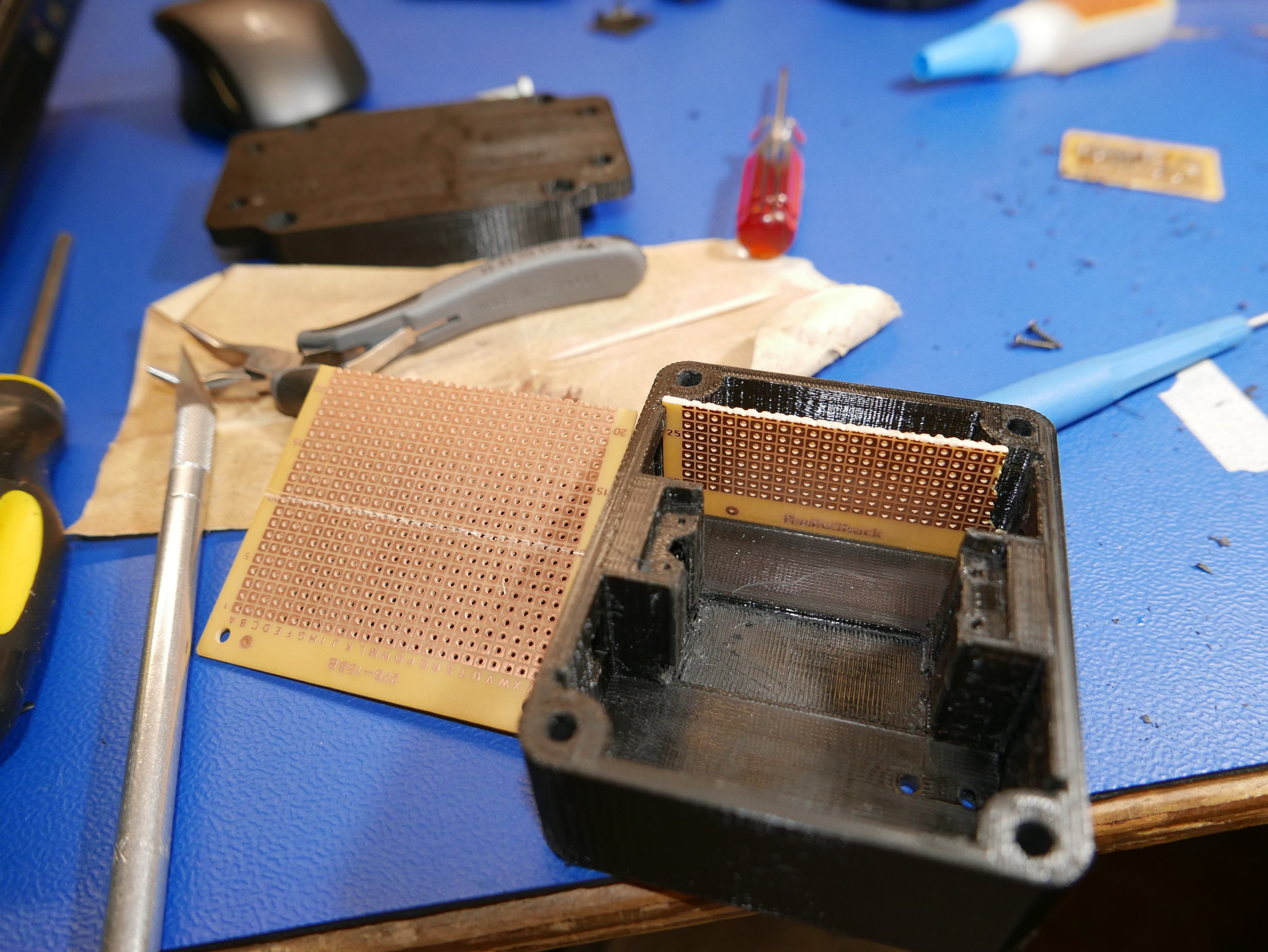
    Right on to the protoboarding. I had a few spare boards left over from old radioshak supplies and they just so happened to be 1/8in longer than needed, so I cut them to size. It took a while to get the Protoboards to fit right as the PCB slots weren't quite 0.063in wide. It took a lot of work with an exacto knife and jewelers files to widen the slots.

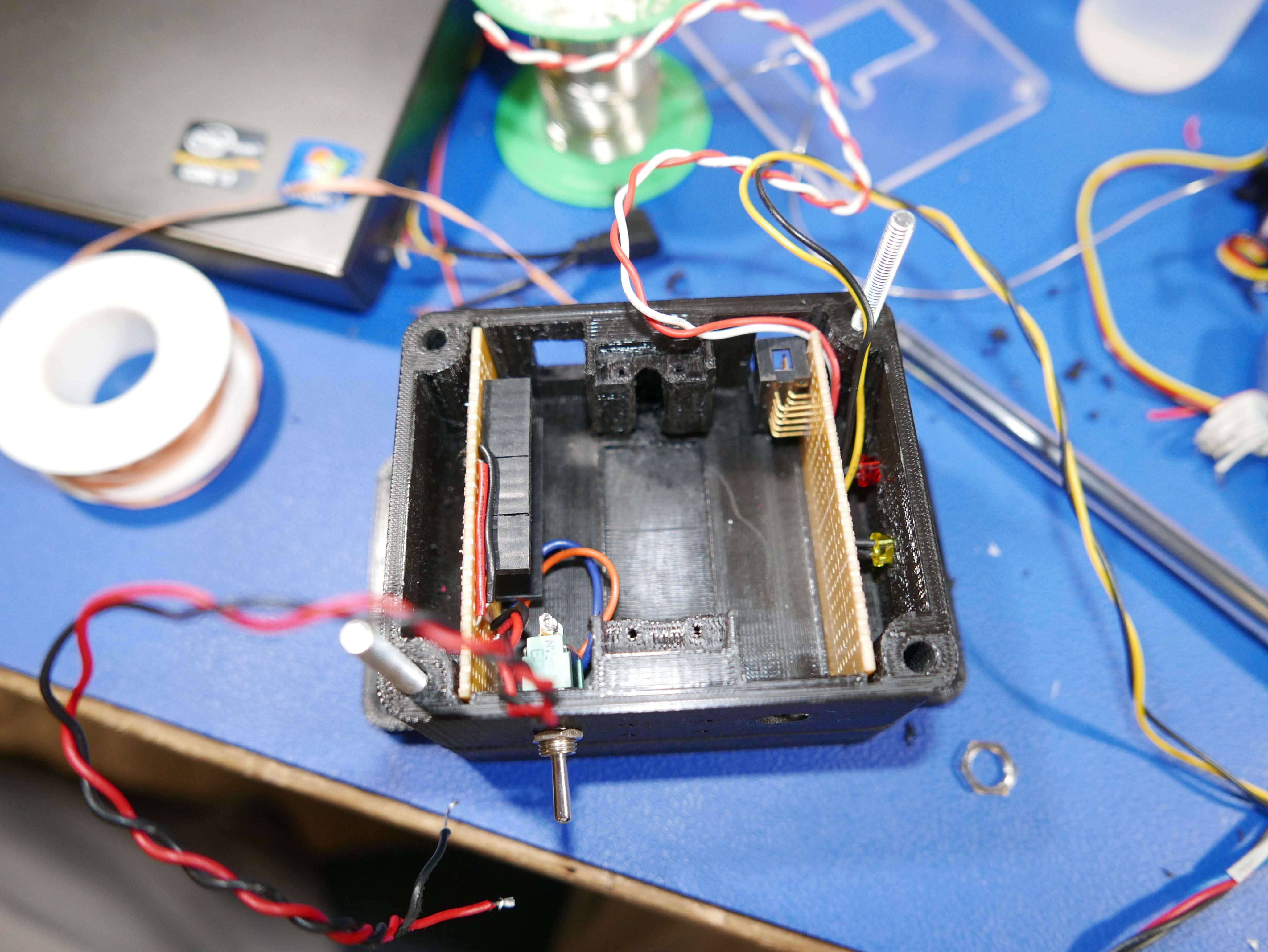
    I wanted a 2 board layout for the unit, one for the control side and the other for expansion / external communication. I added some through hole female 0.1in headers and soldered up the power lines for the arduino. I installed 2 LEDs to serve as programmable indicators. I used an 8x2 0.1in right angle header for the second board.

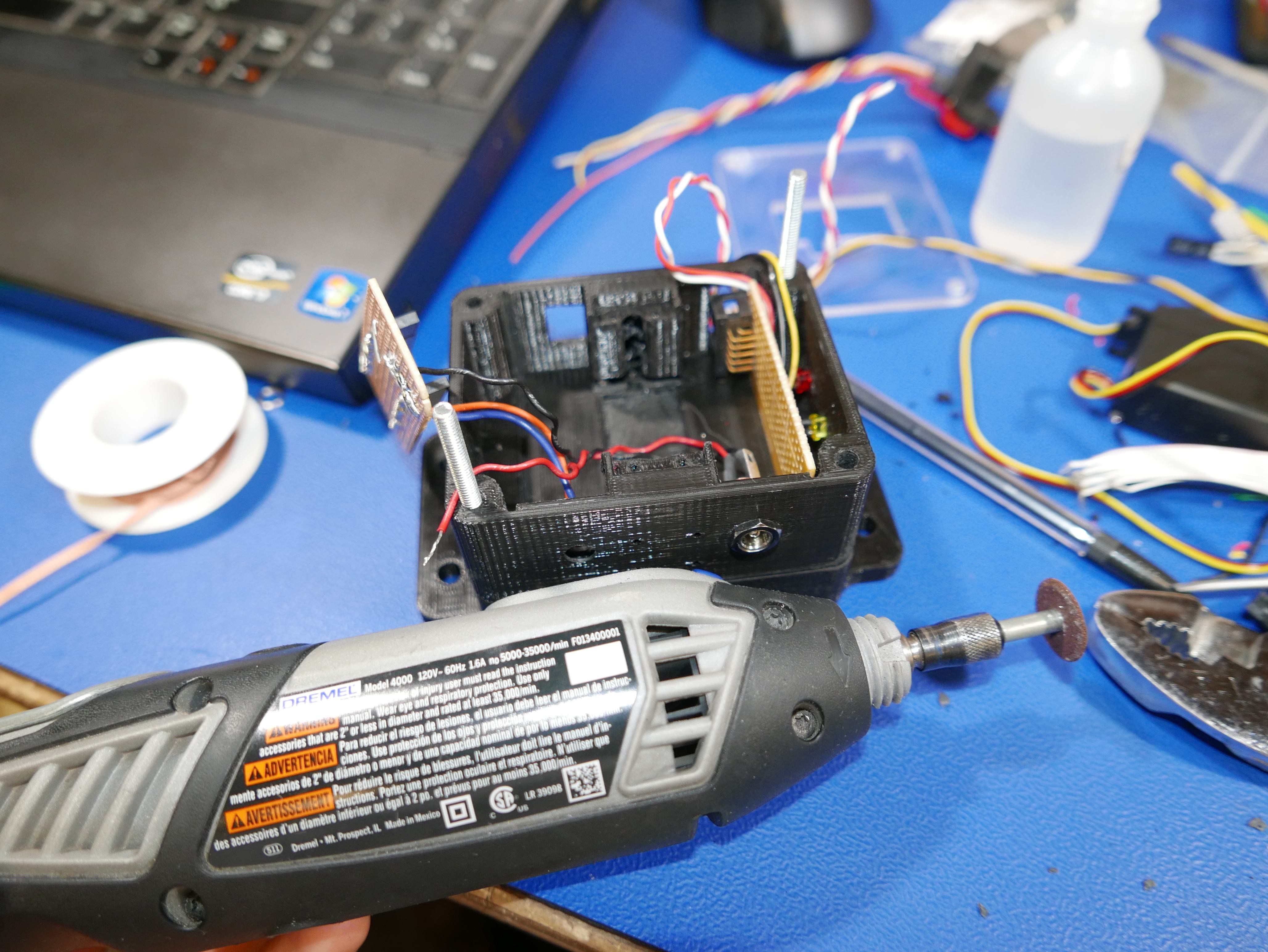
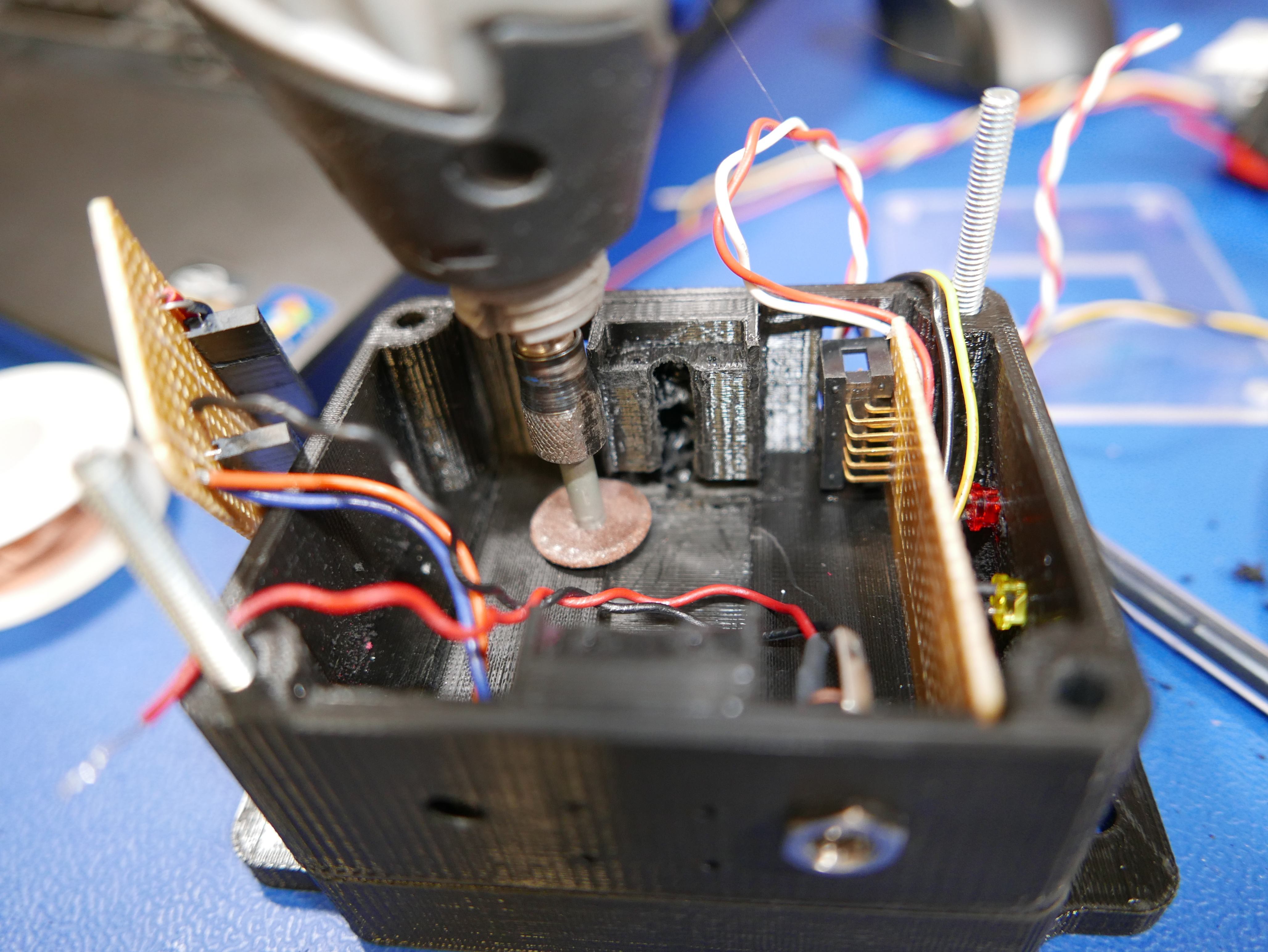
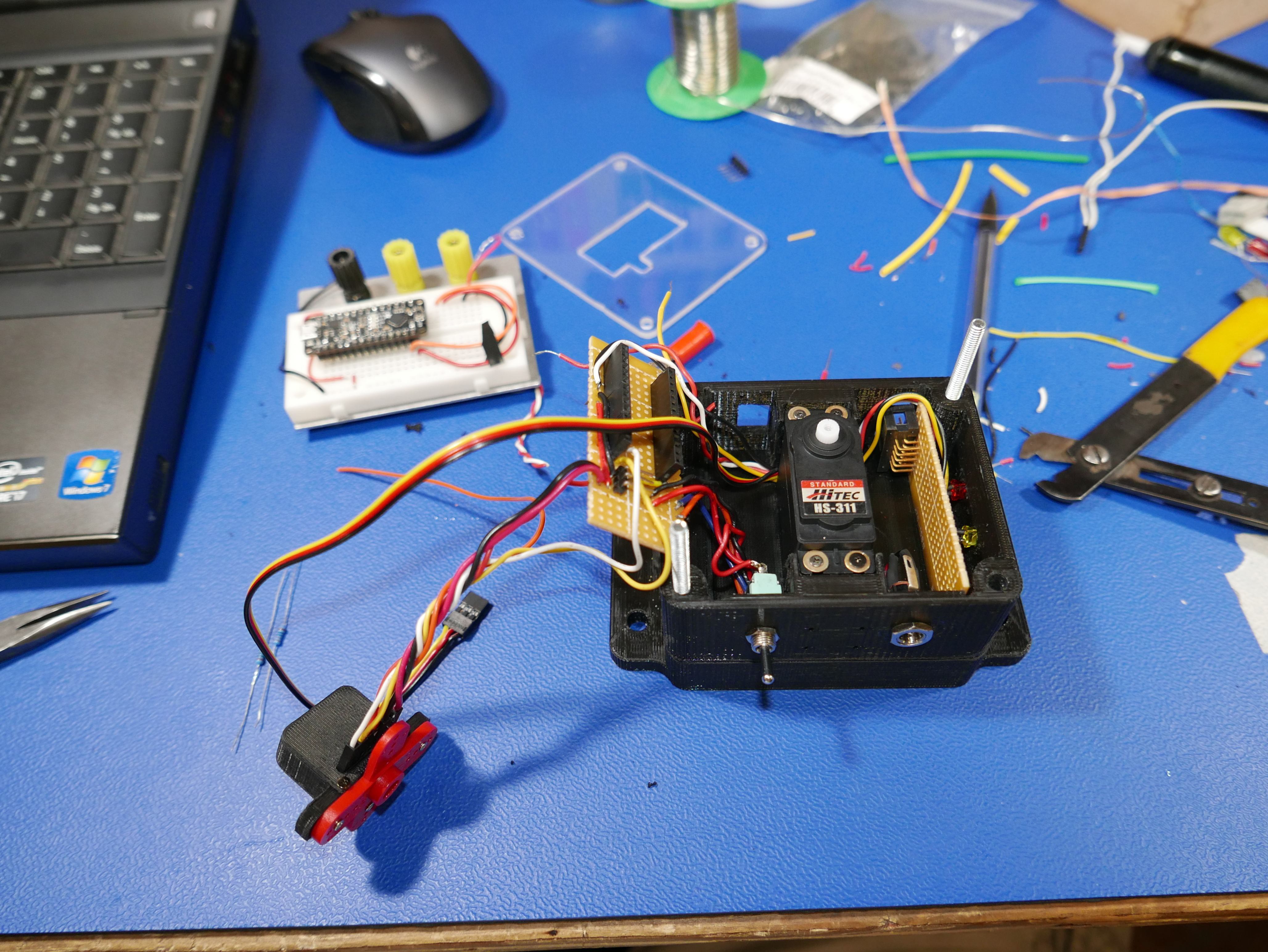
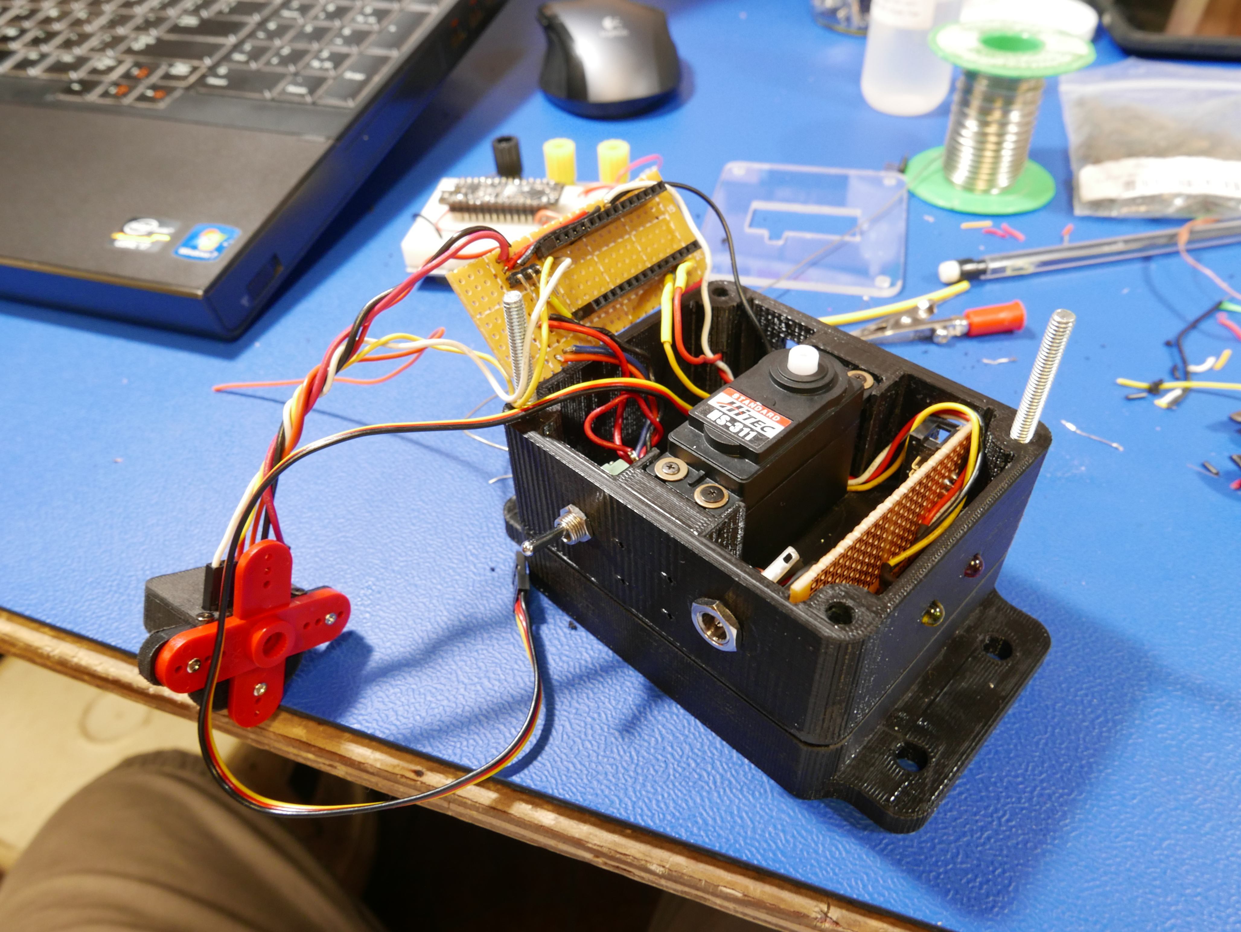
    The hardest part of this project by far and large was fitting the contents of the breadboard in the 3D printed case. It doesn't seem like a lot of components, but the wires take up a lot of space and don't like to move where you want them to go. The wires were thicker than I had hoped and overflowed the channels I designed around the servo motor. I had to dremel out the wire channels a bit to allow for the servo motor to fit properly.

    Here's the mounting of the servo and double checking the fit of the components

    As much as I would have liked to reduce wire length, I had to leave the wires long enough to allow for the two boards to be serviceable, so the extra wire took up more space than desired.

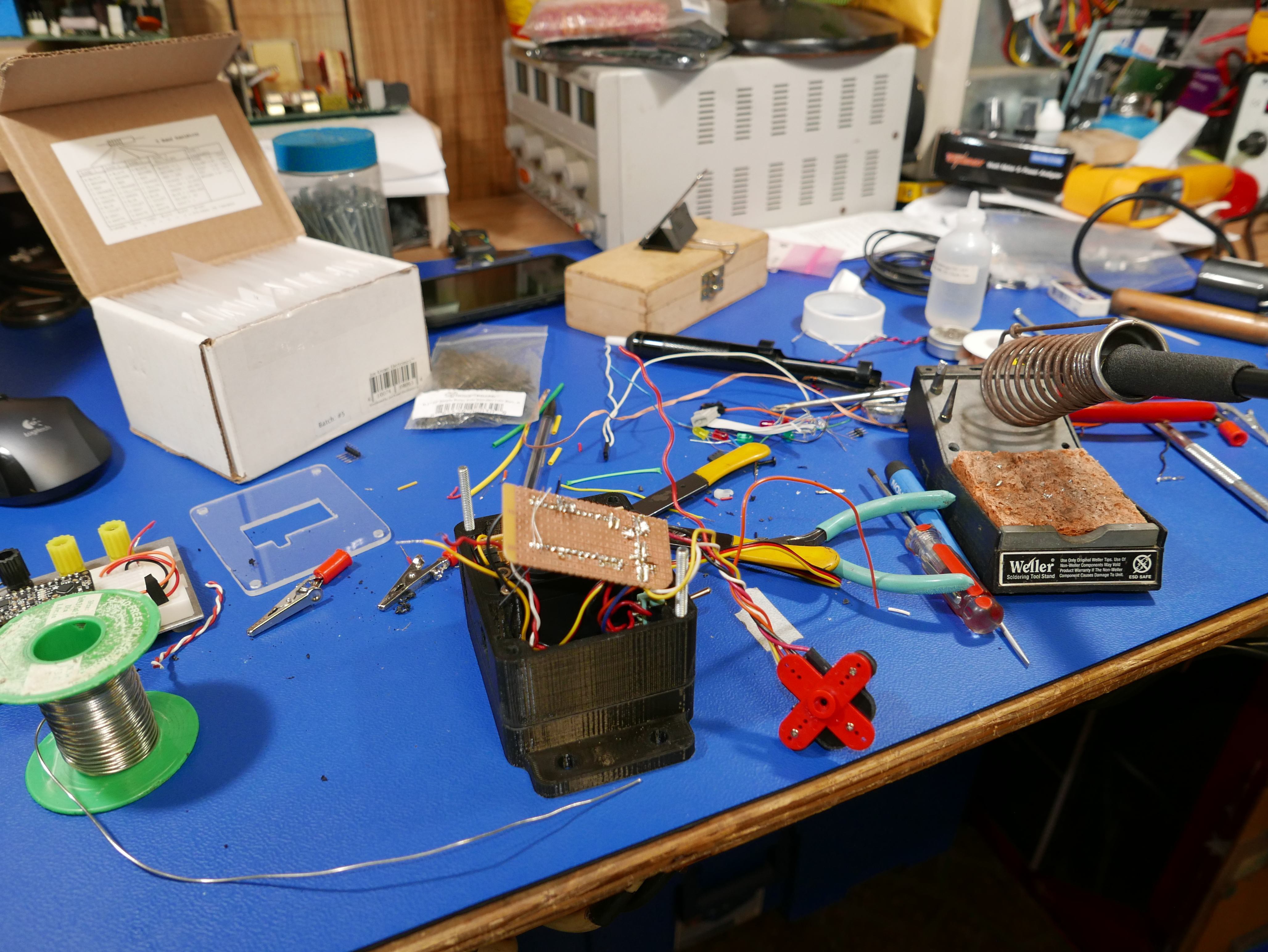
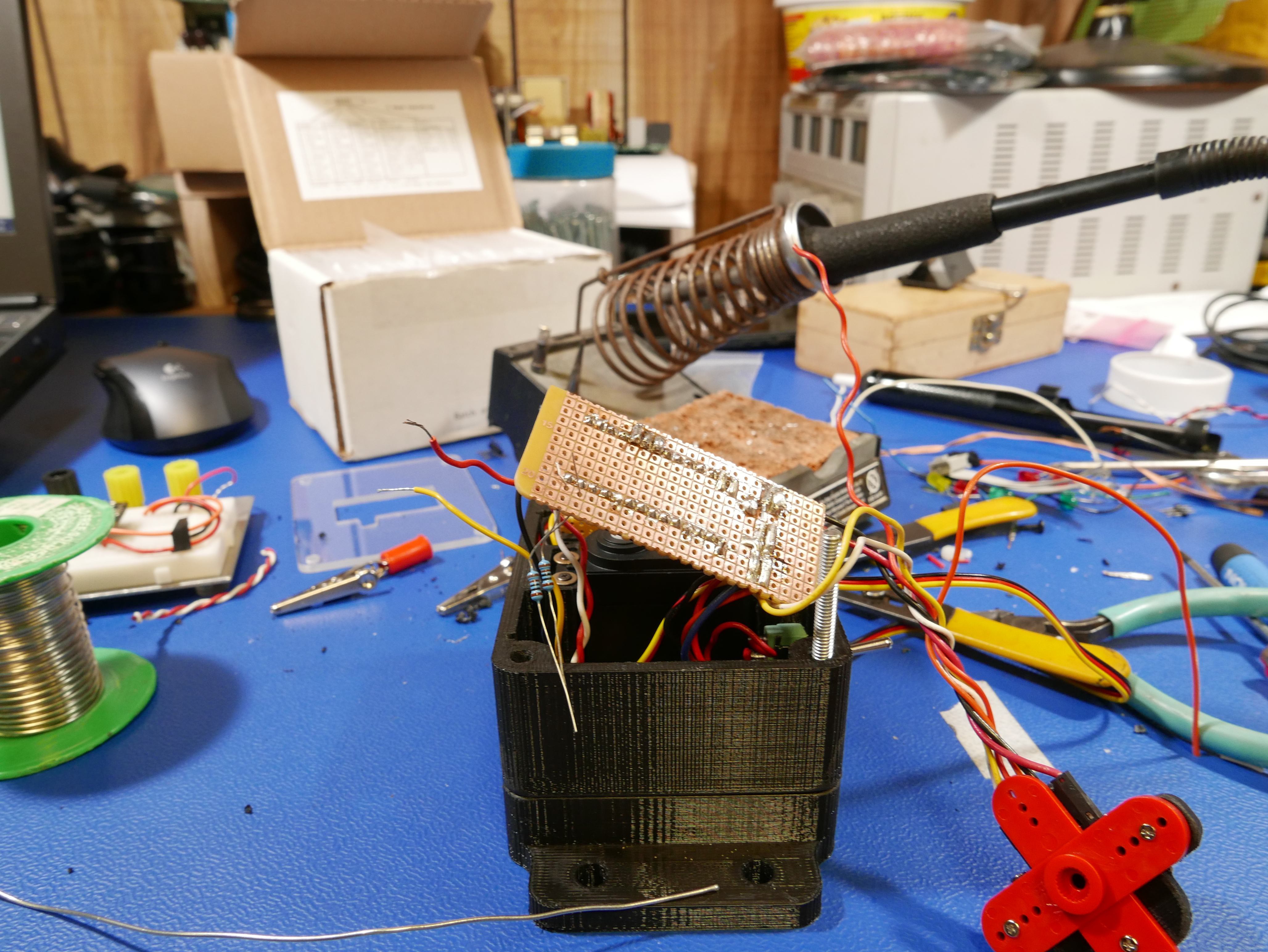
    Busy work table
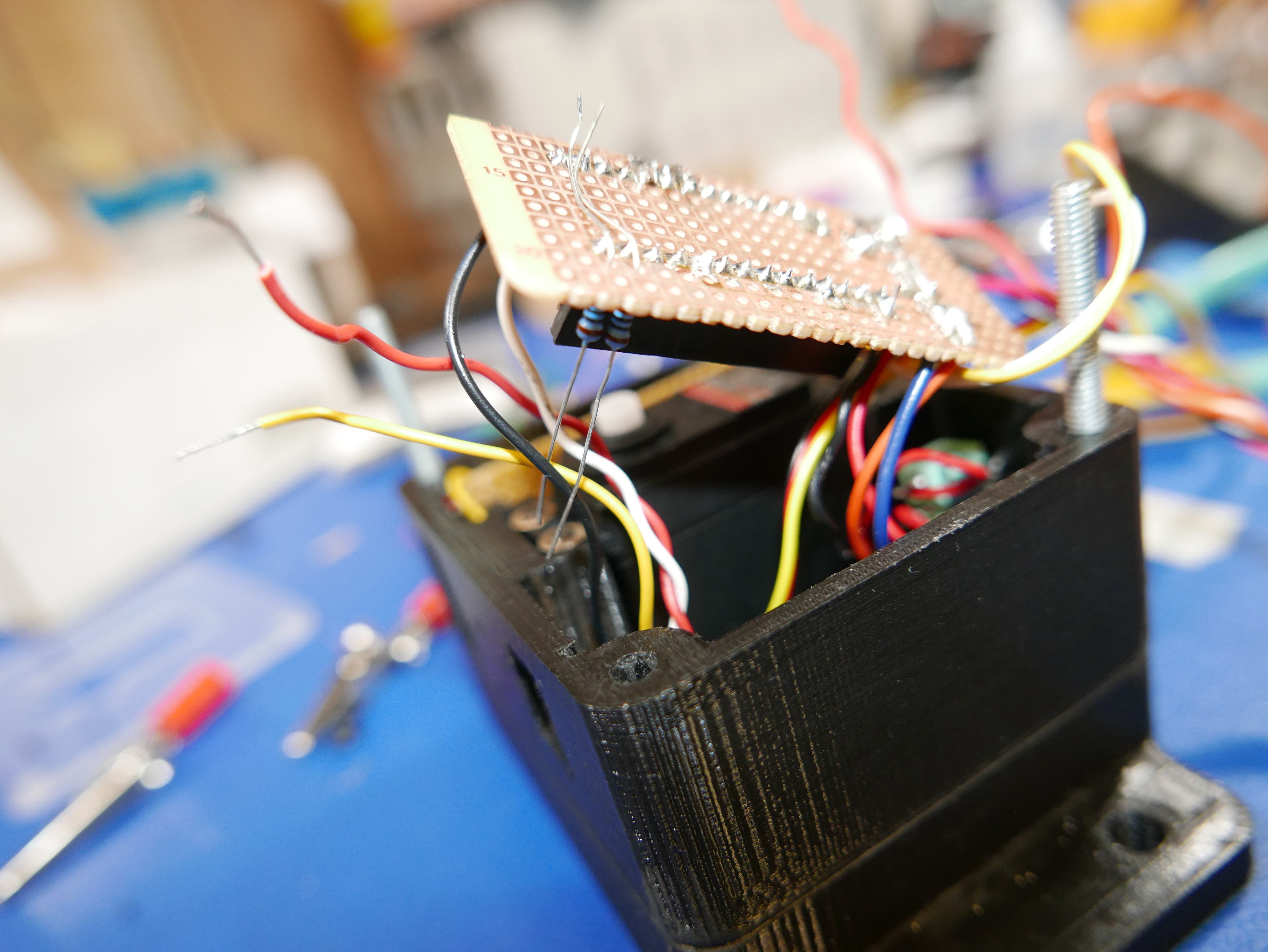
    Resistors for indicator LEDs
    Making it fit
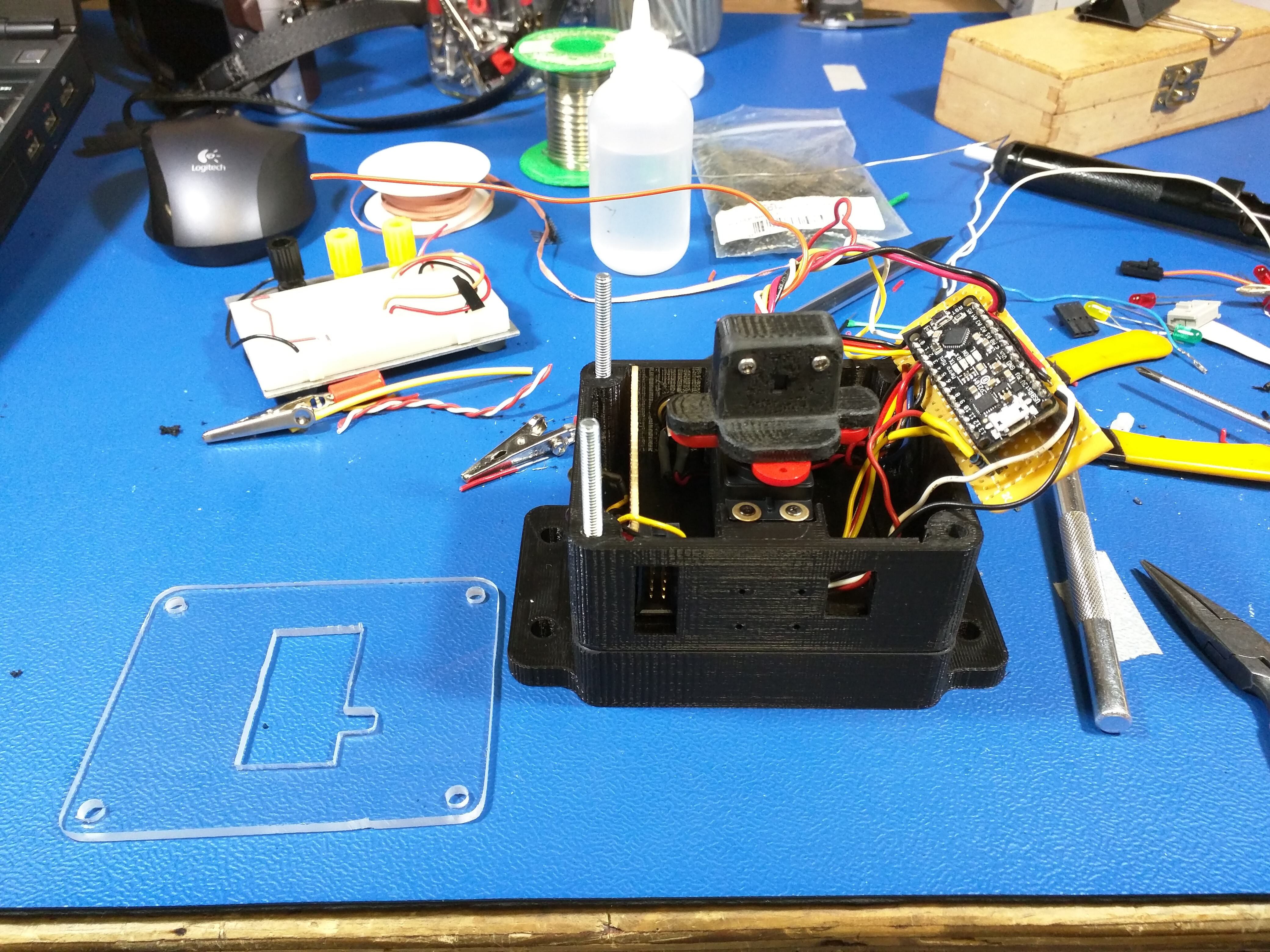
    Final fit before Arduino install

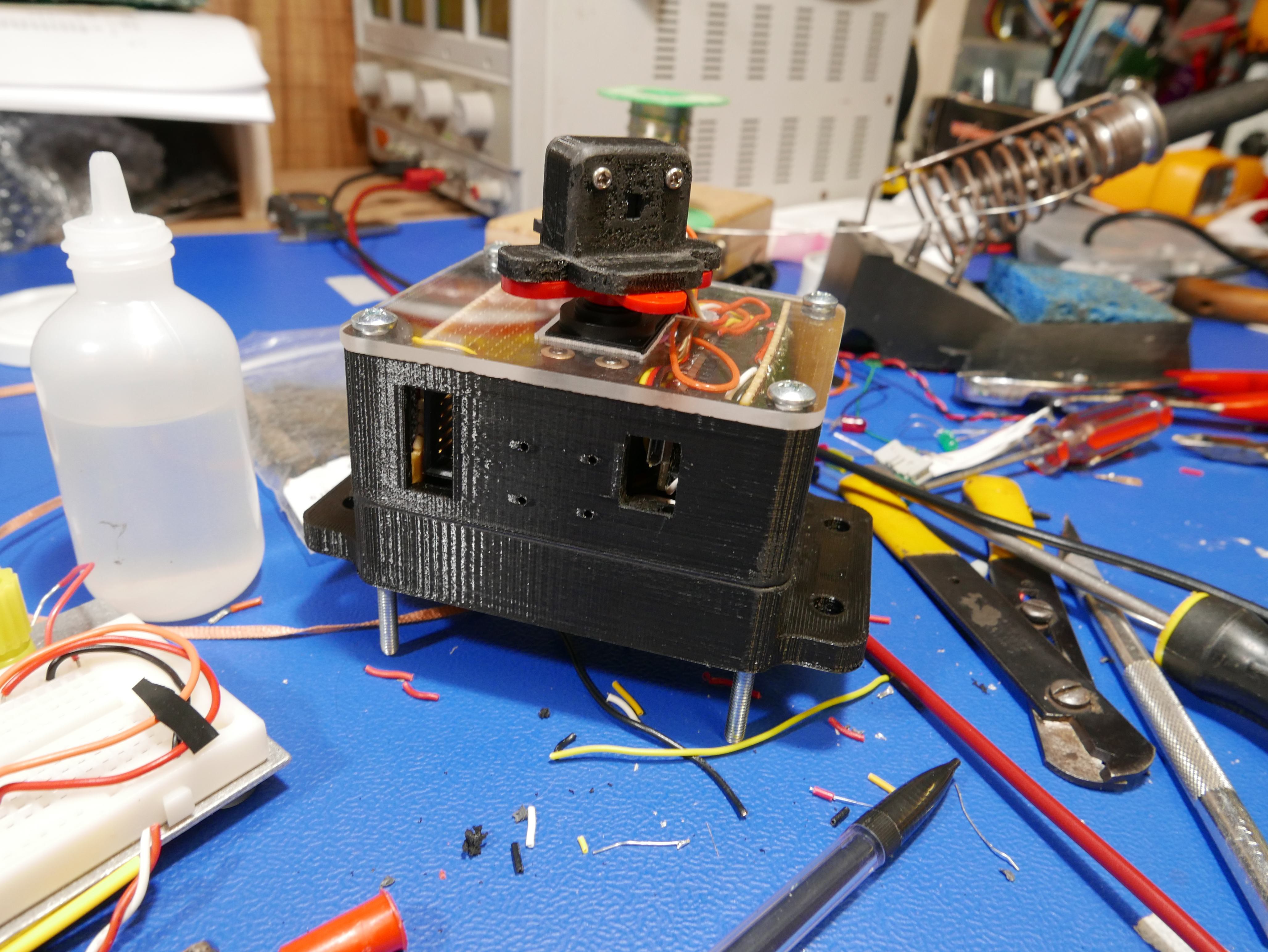
    I used some 8-32 machine bolts to line up the plastic shells and finally installed the Arduino and the remainder of the components.

    It's finally complete!

View all 5 instructions

Enjoy this project?

Share

Discussions

Similar Projects

Does this project spark your interest?

Become a member to follow this project and never miss any updates