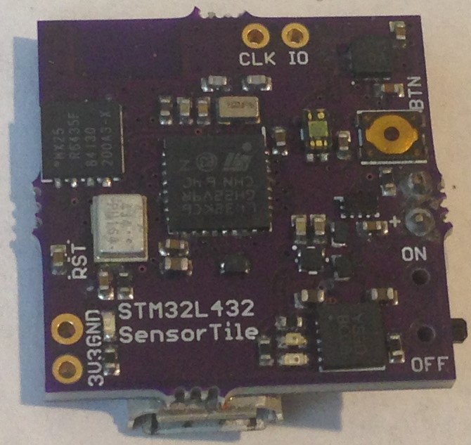
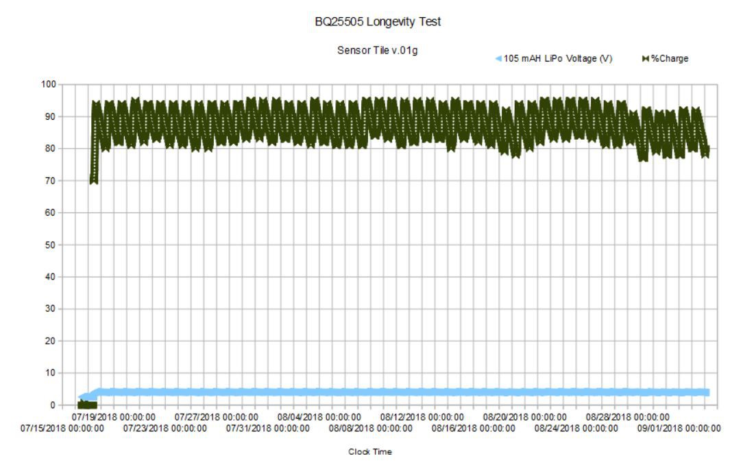
This is a product for sale at Tindie that I designed and use in various projects, including my SensorTile project where I have described its performance in detail.
From the Tindie product page:
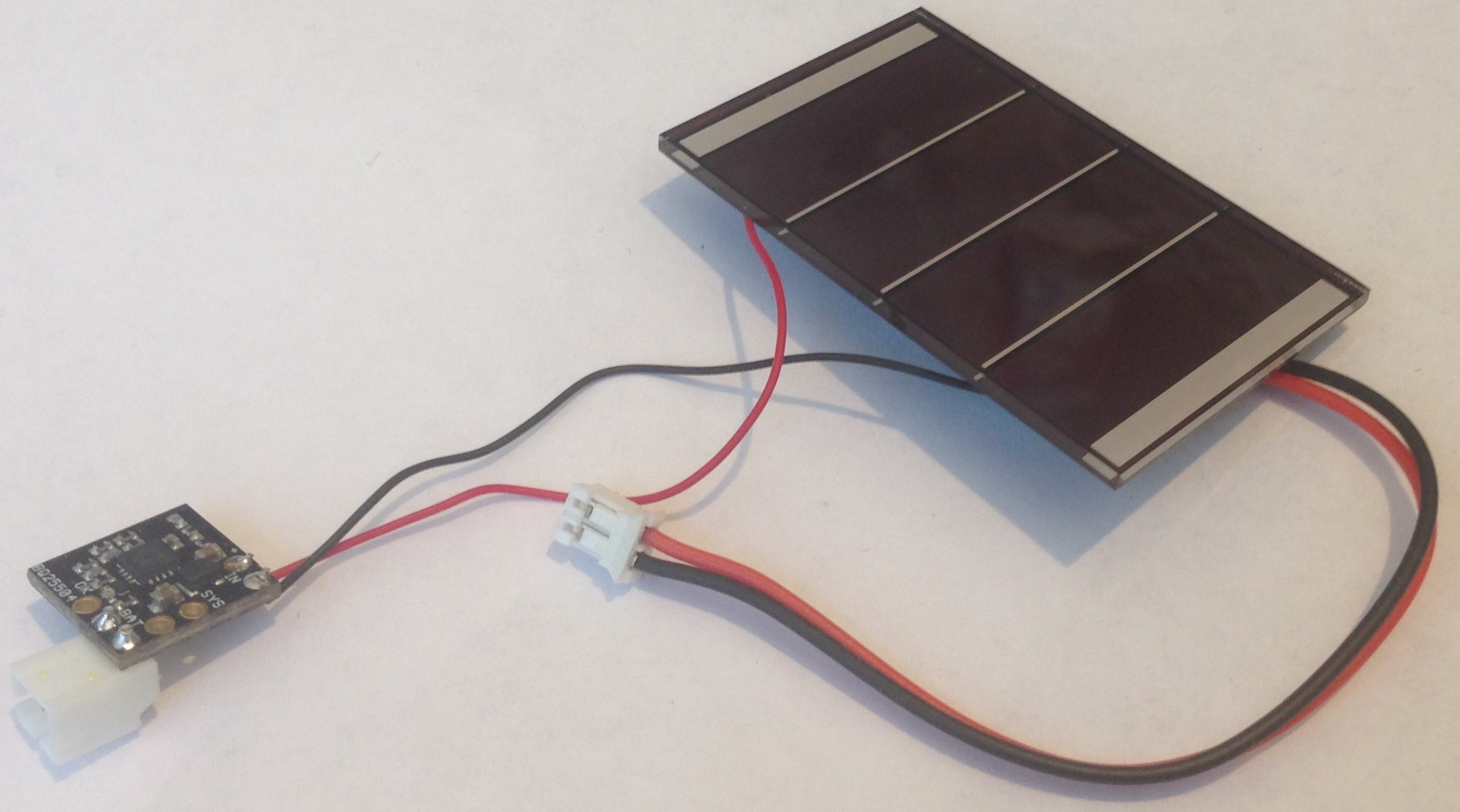
This is a small (0.5 x 0.5 inch) breakout board for Texas Instrument's BQ25504 Ultra Low Power Boost Converter with Battery Management for Energy Harvesting Applications.
From the datasheet: "The bq25504 device is the first of a new family of intelligent integrated energy harvesting nano-power management solutions that are well suited for meeting the special needs of ultra low power applications. The device is specifically designed to efficiently acquire and manage the microwatts (µW) to milliwatts (mW) of power generated from a variety of DC sources like photovoltaic (solar) or thermal electric generators. The bq25504 is the first device of its kind to implement a highly efficient boost converter/charger targeted toward products and systems, such as wireless sensor networks (WSNs) which have stringent power and operational demands. The design of the bq25504 starts with a DC-DC boost converter/charger that requires only microwatts of power to begin operating."
The BQ25504 is a high-efficiency boost converter of great flexibility that can be used to charge a battery using energy harvesting from a variety of sources. Here I have chosen to set the parameters of the boost converter to charge a standard one-cell, 4.2 V LiPo battery like this one. The BQ25504 employs a Maximum Power Point Tracking (MPPT) method which regulates the input impedance of the charger to maintain maximum efficiency of the solar cell. I have set the MPPT to 78% of the open-circuit voltage of the solar cell.
The BQ25504 protects the LiPo battery from undervoltage, which can cause damage through excessive discharge, as well as overvoltage to prevent excessive charging. The over- and under-voltage protection thresholds are set by a resistor network which I have chosen to limit discharging to 3.27 V and over charging to 4.27 V.
There is a battery OK threshold of 3.58 V and a battery hysteresis threshold of 3.78 V. The battery OK pin will toggle to LOW when the battery voltage falls below 3.58 V. The battery OK pin will toggle to HIGH when the battery voltage rises above 3.78 V. In other words, on decreasing battery voltage (due to discharging) the interrupt will fall and stay LOW (and the on-board green led will go out) below 3.58 V, and on increasing battery voltage (due to charging) the interrupt will rise and stay HIGH (and the green led will remain on) above 3.78 V. The battery OK pin allows an MCU to monitor the state of the battery charge. The idea is that the MCU can detect when the battery OK pin falls to the LOW logical condition (a sort of interrupt) and limit large loads until the solar cell is able to recharge the battery to a sufficient level to support the large current draw.
It sounds complicated, and it takes some time to get your arms around all of the detail in the data sheet, but it is really straightforward to use the BQ25504 in your applications. Connect the solar cell to the IN port, the LiPo battery to the BAT port. Use the OK pin as a battery charge detection interrupt and simply connect the SYS power (3.3 - 4.3 V!) and GND to the VIN/GND pins of your MCU.
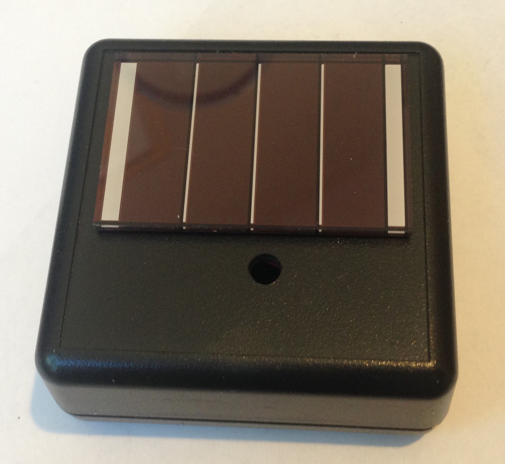
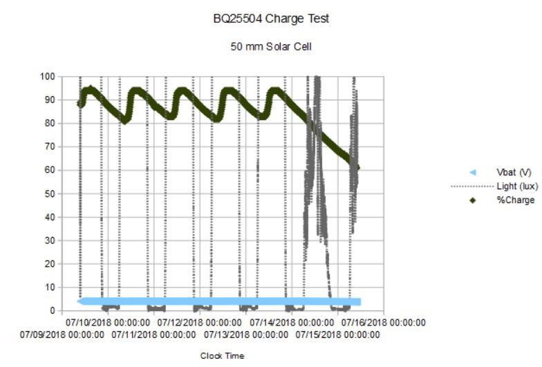
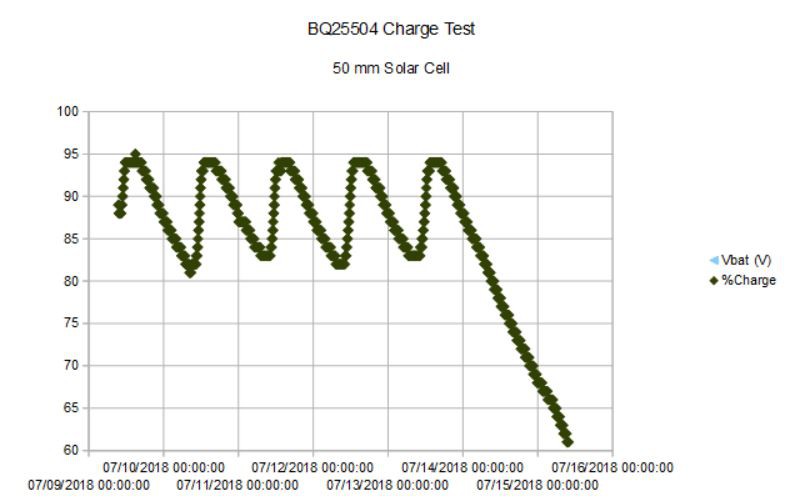
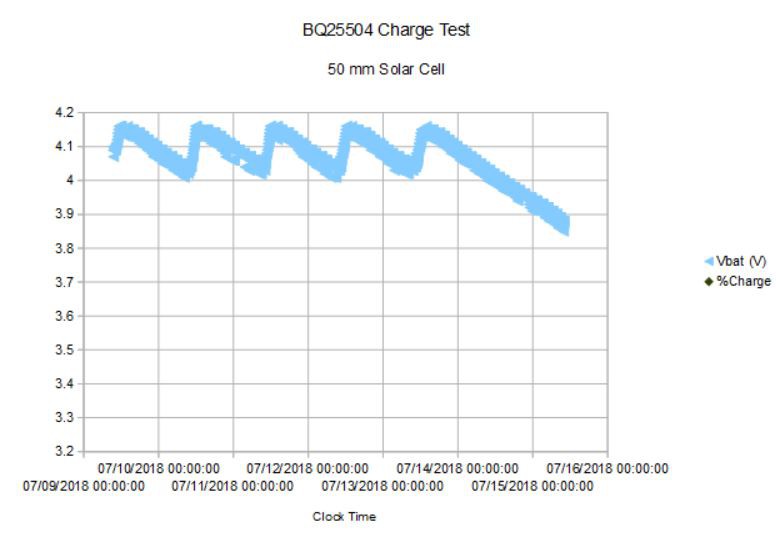
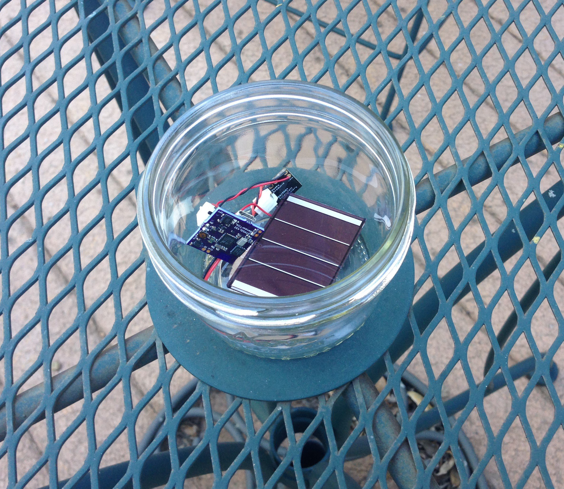
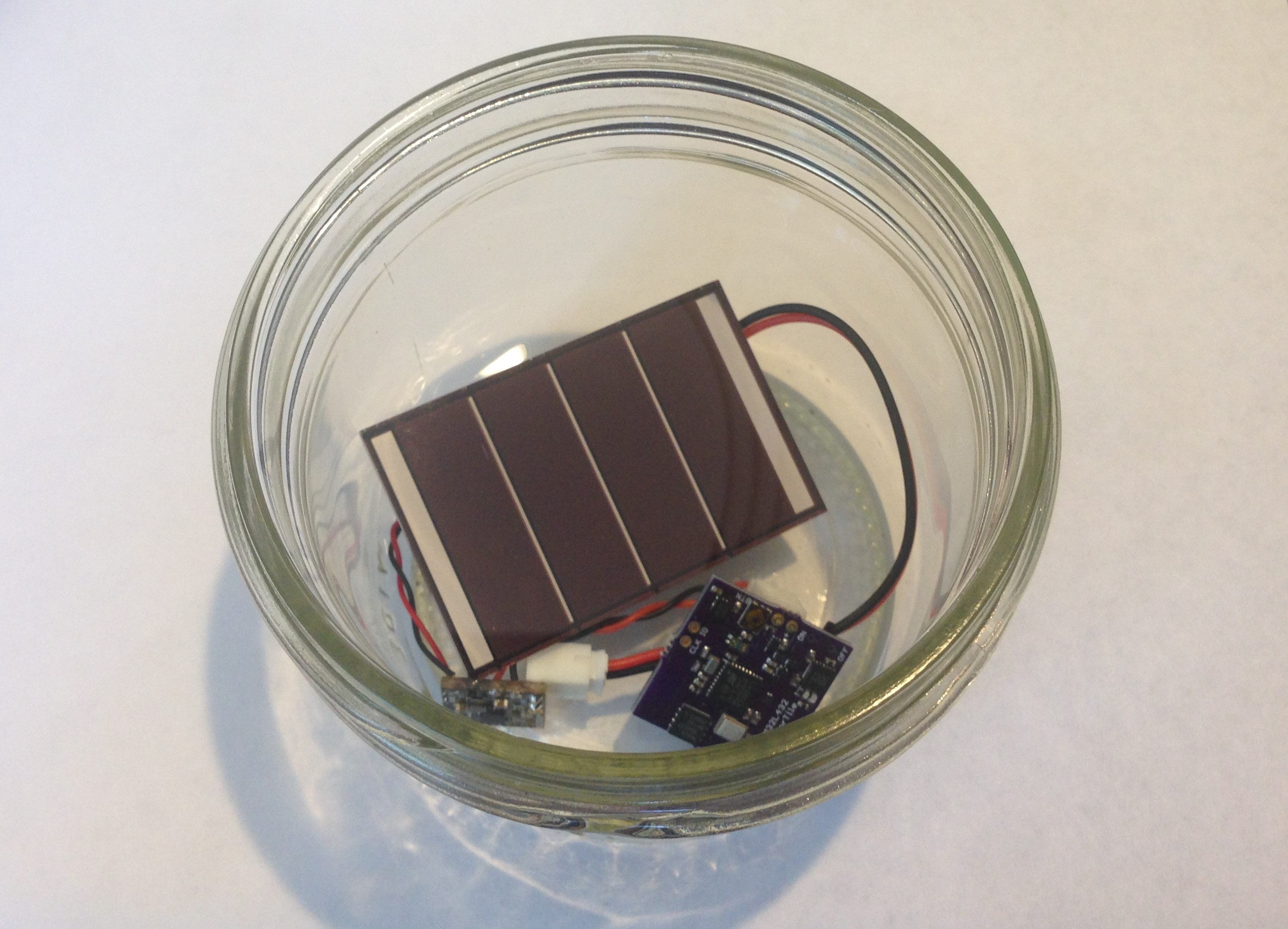
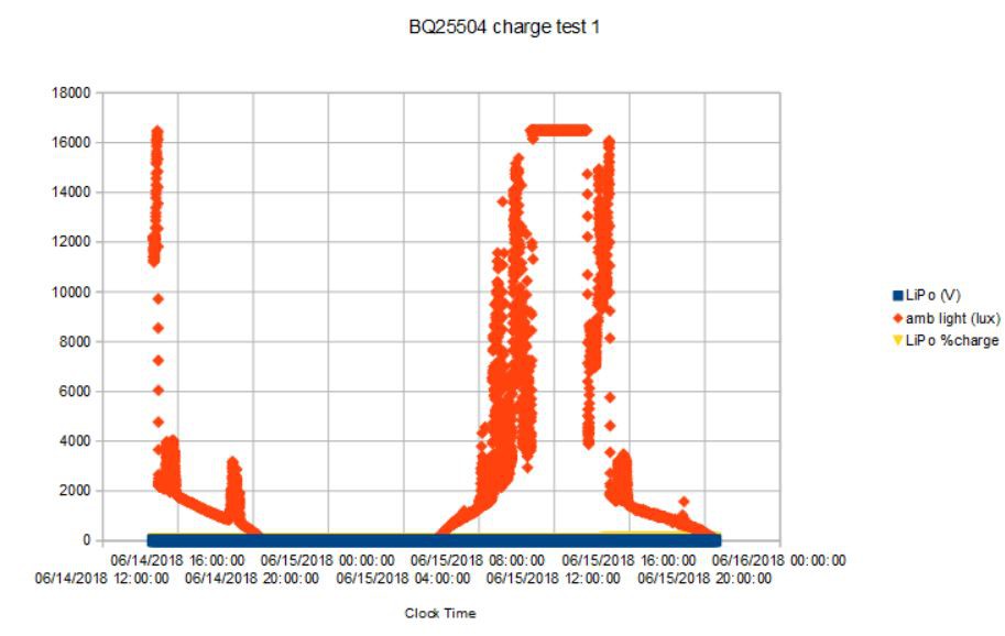
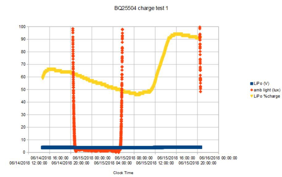
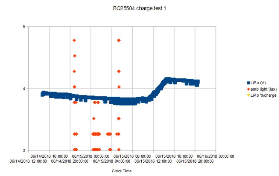
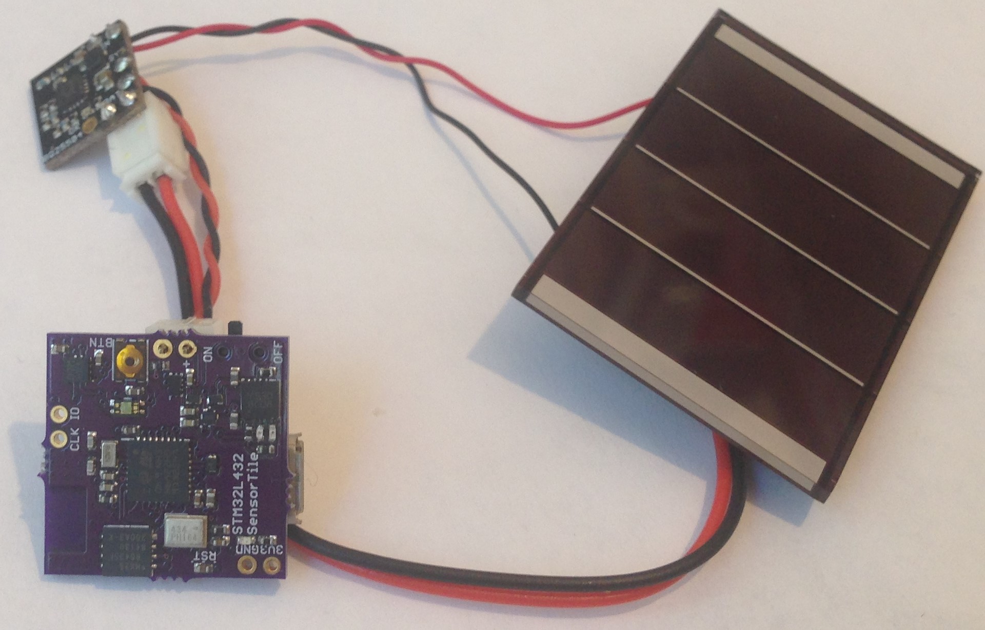
I have been using the BQ25504 along with this small 2.2V solar cell to power my SensorTile Environmental Data logging project. I have found that with 6 hours of direct sun (~20 klux) I am generating an average of ~7 mA per hour (at >90% efficiency!), just enough to keep the 1.8 mA Sensor Tile running indefinitely. You can read more about this and see plots of the charge versus time in the project logs.
 Kris Winer




 CriptasticHacker
 Justin Maynard
 Drew Pilcher
Can I ask why you choose such unusual charging limits?
Usually keeping a lithium above 3V (particularly with this low charging current) is good enough to not add additional damage, but keeping it at 3.3V won't lose too much run time and is probably better for it, so I sort of understand this decision.
(Edit, just realised this is probably to keep the chip running at above ~3.3v?)
However where these batteries typically see wear and tear is above 4V, you then choose a 4.27v max voltage?!
I'm sure you had reasons, it just seems odd.
I can't remember the exact numbers, but a lithium charged to 4v instead of 4.2, will still get something like 80% of the capacity and see about 1/4 of the degradation.