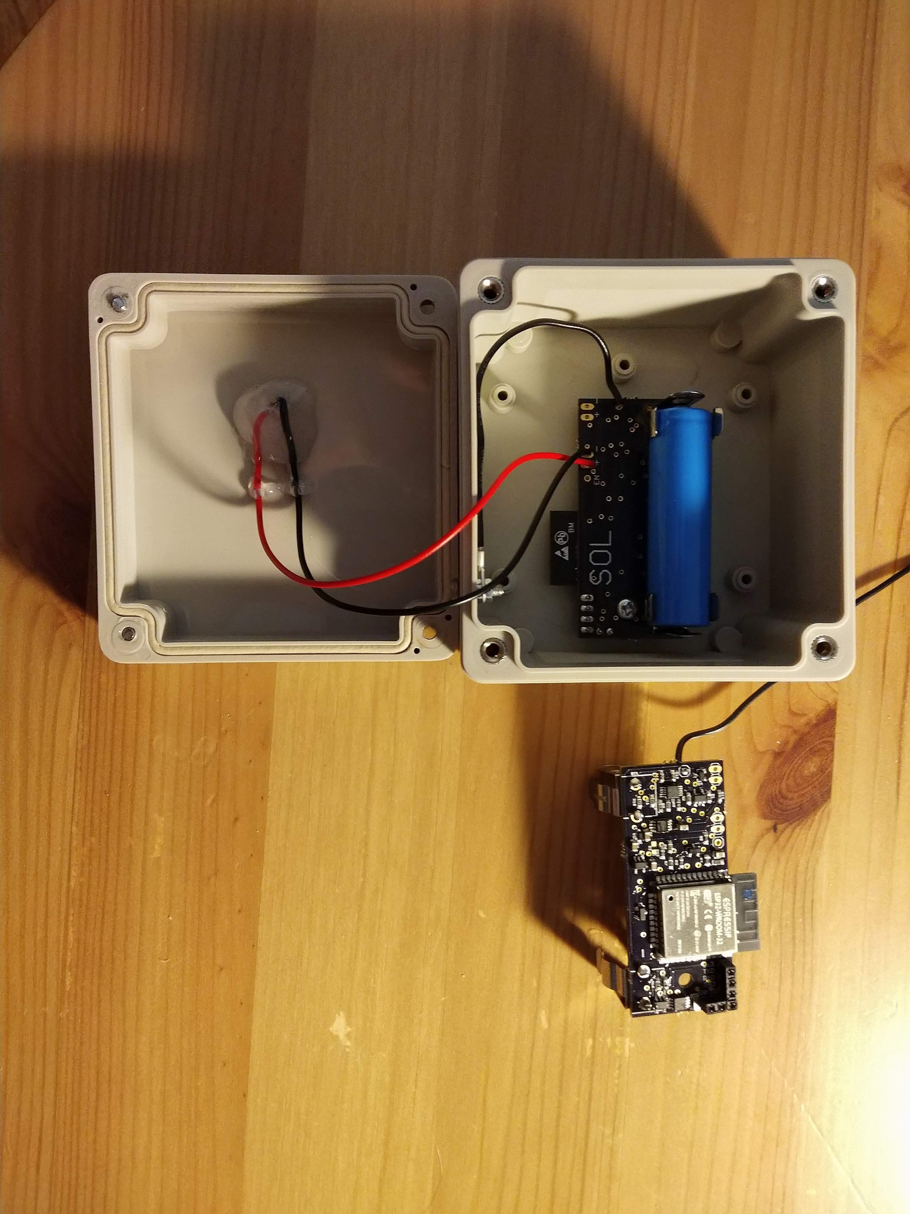
Working off some of the successes and failures of version 1, I recently designed and built a second version of SOL. There were a variety of goals here:
- Lower BoM cost
- Some lower cost replacement parts
- Smaller PCB size
- Smaller battery (from 16500 to 14500 Lithium battery)
- External ADC for power measurement (ESP32 ADC has known accuracy issues, discussed here)
- Use ADC with PGA for higher accuracy measurement in low-light situations
- RTC for time-stamping datapoints
- Temperature sensor (ESP32 temperature sensor is very inaccurate)
- Better mounting in case
- SOL V1 overall size was slightly wrong, so didn't fit cleanly into its waterproof case
- Easier to program -- expose IO0, IO2, and EN pins
I will be adding the BoM, design files, and firmware for SOL V2 soon. For now, some pictures of the two assembled devices made so far:

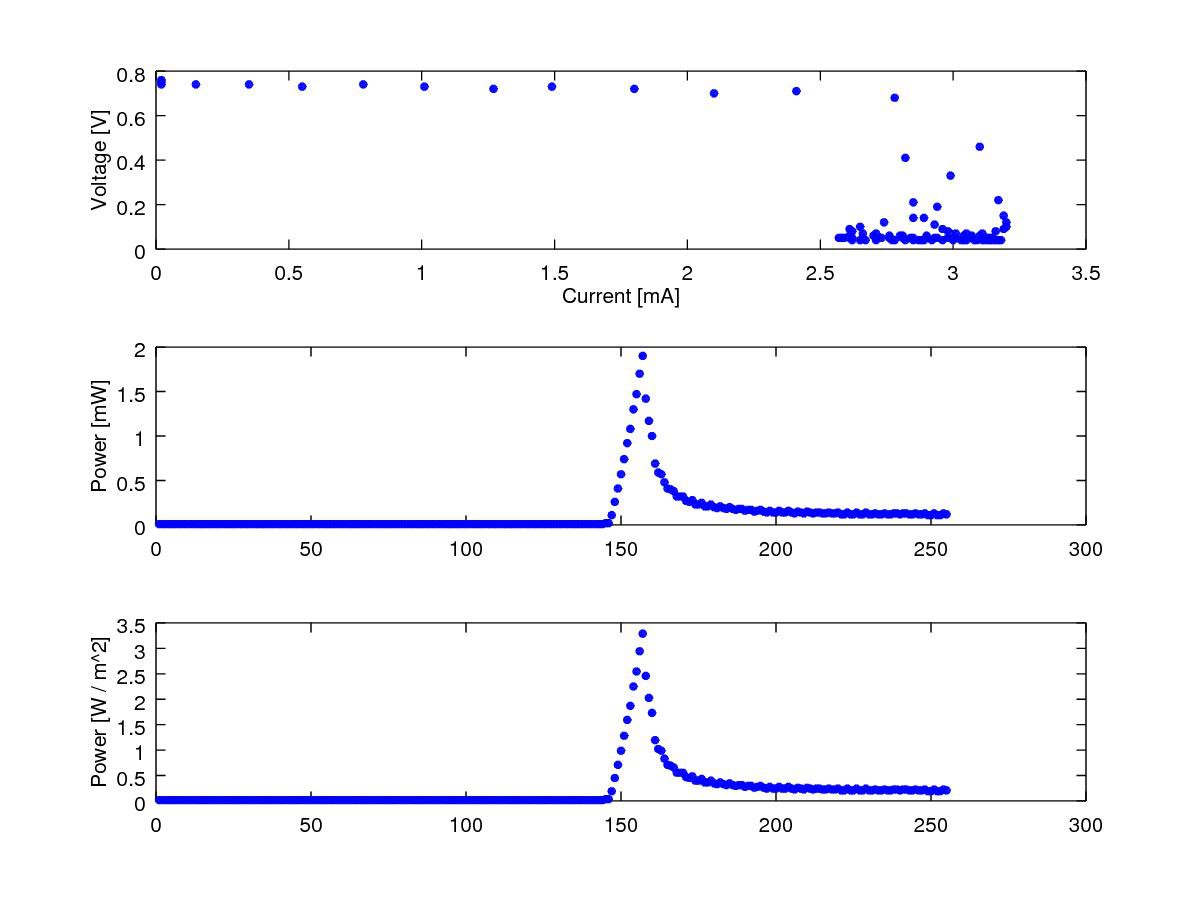
I tested the power measurement sub-circuit, using 5 difference settings of the ADC PGAs (4.096V, 2.048V, 1.024V, 0.512V, and 0.256V full scale ranges.) With the amount of light available (indoor lamp in a mostly dark room), the ADC did not saturate at any PGA level, and the scaled measurements all matched nicely. One example is shown below. A fairly typical solar panel IV curve can be seen in the top subplot. Overall, the levels of measurement seems lower than expected, but I will need to see its performance in direct sunlight to check if it is ballpark correct. For reference, at maximum power this panel should be about 5.5V and 100mA. Note the power density subplot at the bottom is assuming a panel efficiency of 15%, and it just for reference.

Discussions
Become a Hackaday.io Member
Create an account to leave a comment. Already have an account? Log In.