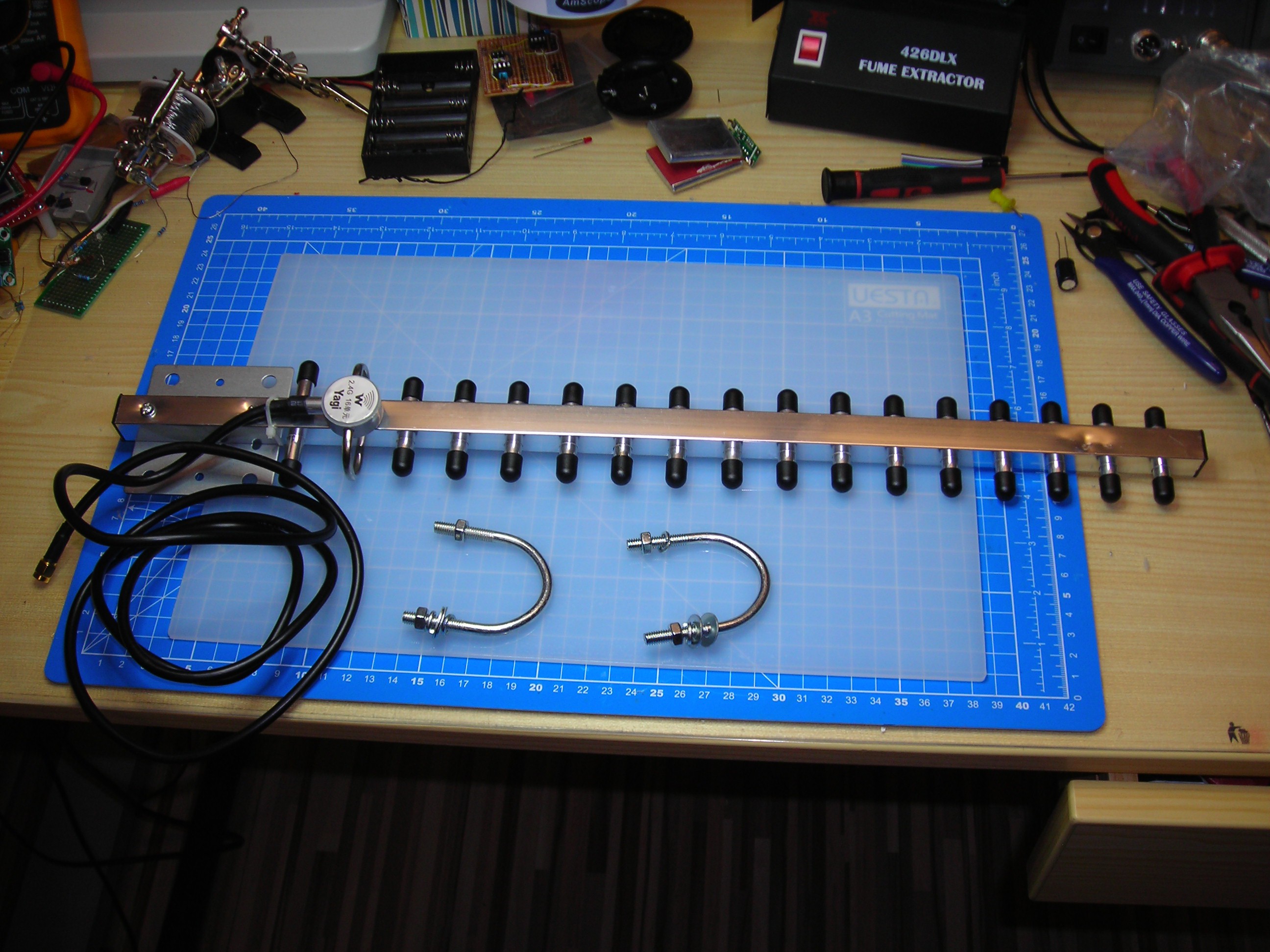
So I recently bought two 2,4GHz Yagis from different sellers on AliExpress for ~12€ each.
The first one was actually not for me but for a friend who is trying to extend the range of his WiFi-dependent drone. Mine serves primary as a range extender for my home WiFi so that I have access to the music server when BBQ'ing in the garden (and my smartphone-addicted friends can use Spotify or WhatsApp or whatever).
Both antennas had EXACTLY the same dodgy assembly 'mistakes' documented here (The first one was fixed in the same way, but I didn't document it from start to finish).
There seem to be a lot of similar antennas on eBay, AliExpress etc. and these could be common problems with many of them not working as intended, so I decided to document my findings.
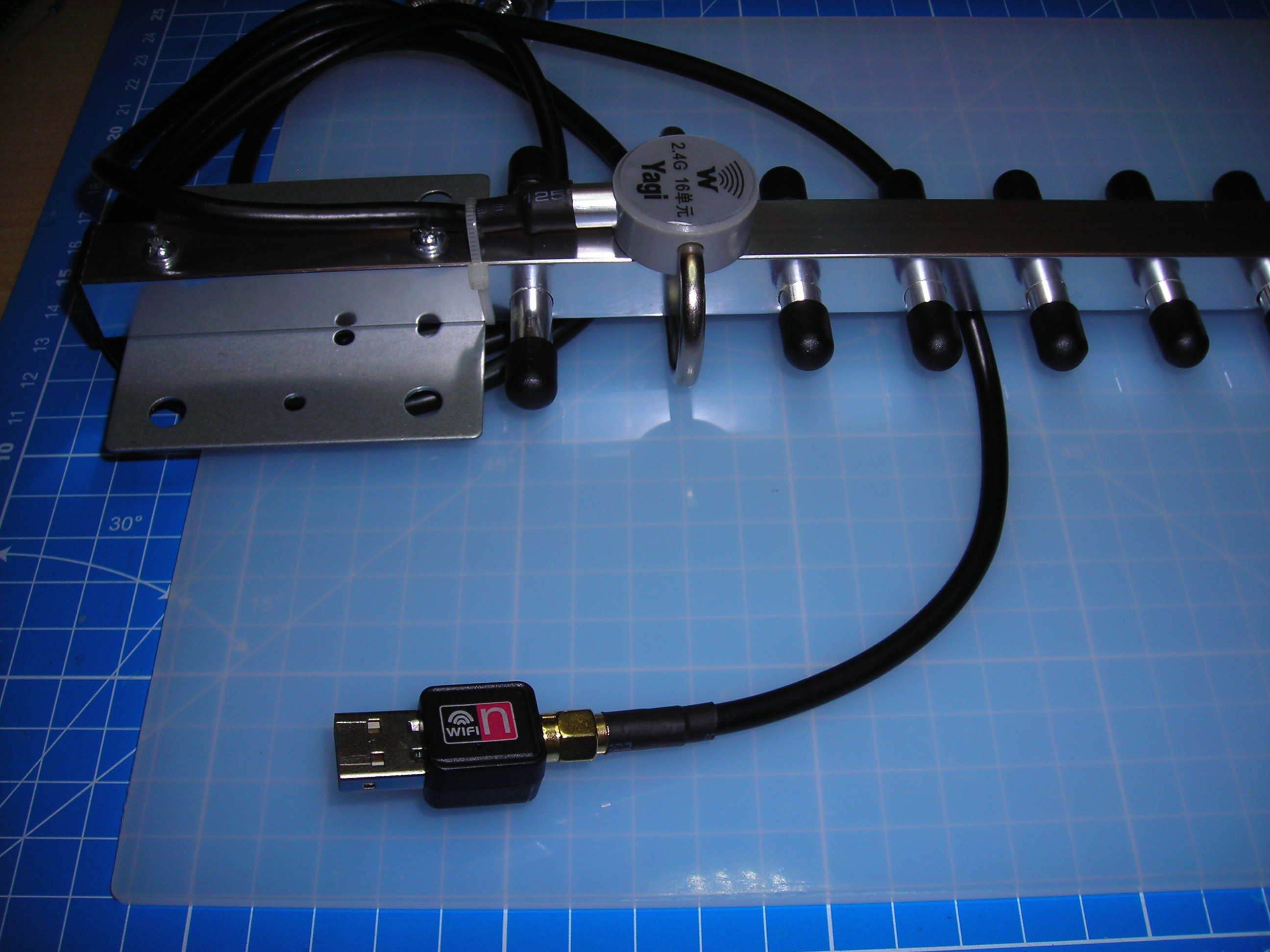
Upon the first test via a Ralink USB WiFi-Dongle I noticed that the reception was actually worse than the integrated WiFi of my Laptop.
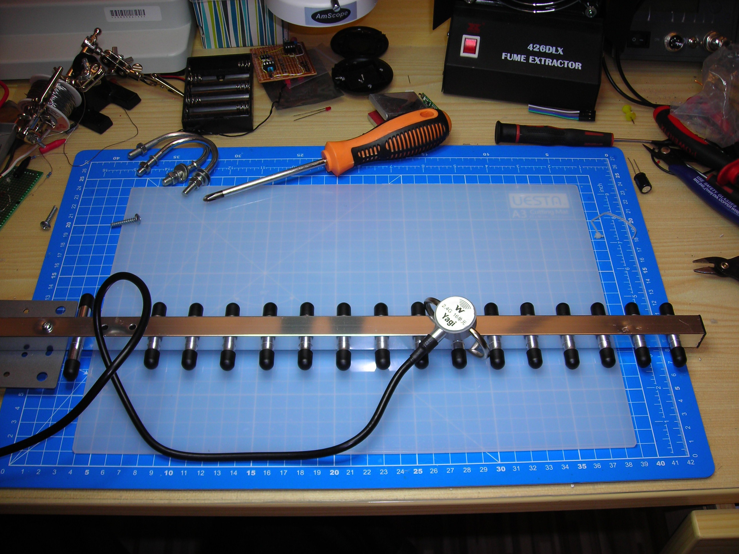
The length and spacing of the director rods / tubes also seems a little too even - a 'properly' calculated Yagi should perhaps have some more variation, for example as explained by this excellent tutorial here:
https://www.ab9il.net/wlan-projects/wifi6.html
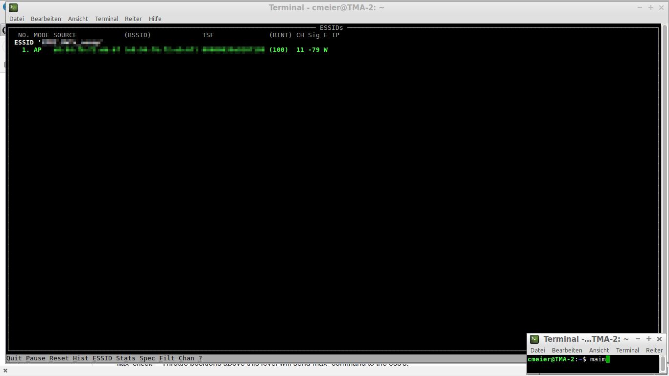
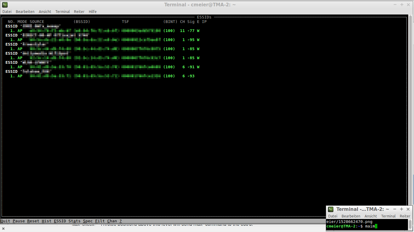
Investigating further with "horst", a Linux WLAN monitoring and troubleshooting tool, I discovered that the antenna had no directionality at all, there was poor reception and signal strength regardless of the way it was pointed in regard to my (and my neighbor's) router / access points. It could only pick up the closest access point and displayed a very modest signal strength.
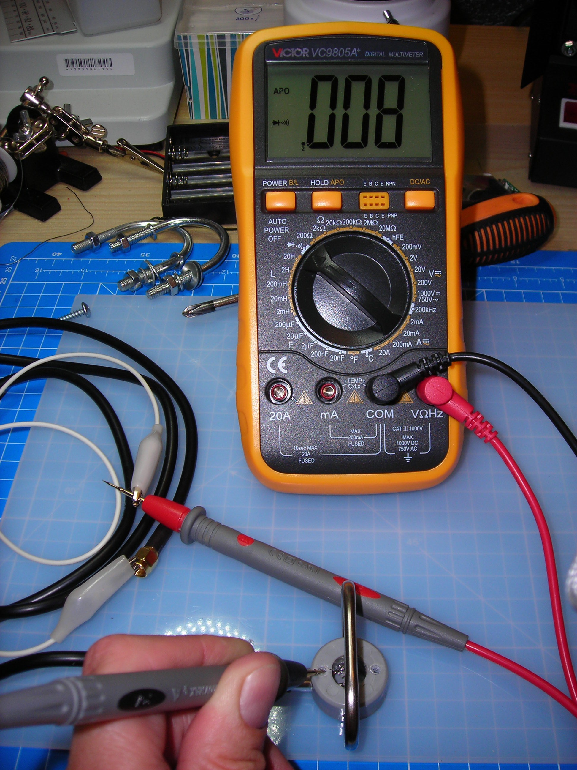
First thing I noticed when checking for continuity on the antenna cable was that the antenna frame was connected to the shielding AND the core of the coax wire (!).
According to Wikipedia, the antenna frame and the director/reflector rods of a Yagi should NOT be electrically connected at all.
https://en.wikipedia.org/wiki/Yagi%E2%80%93Uda_antenna
The active element CAN be a "folded dipole", that means the core and the shielding of the coax are connected to the opposite ends of a loop-style antenna element like the one used in this Yagi, so continuity between shielding and core alone would be intentional.
https://en.wikipedia.org/wiki/Dipole_antenna#Folded_dipole
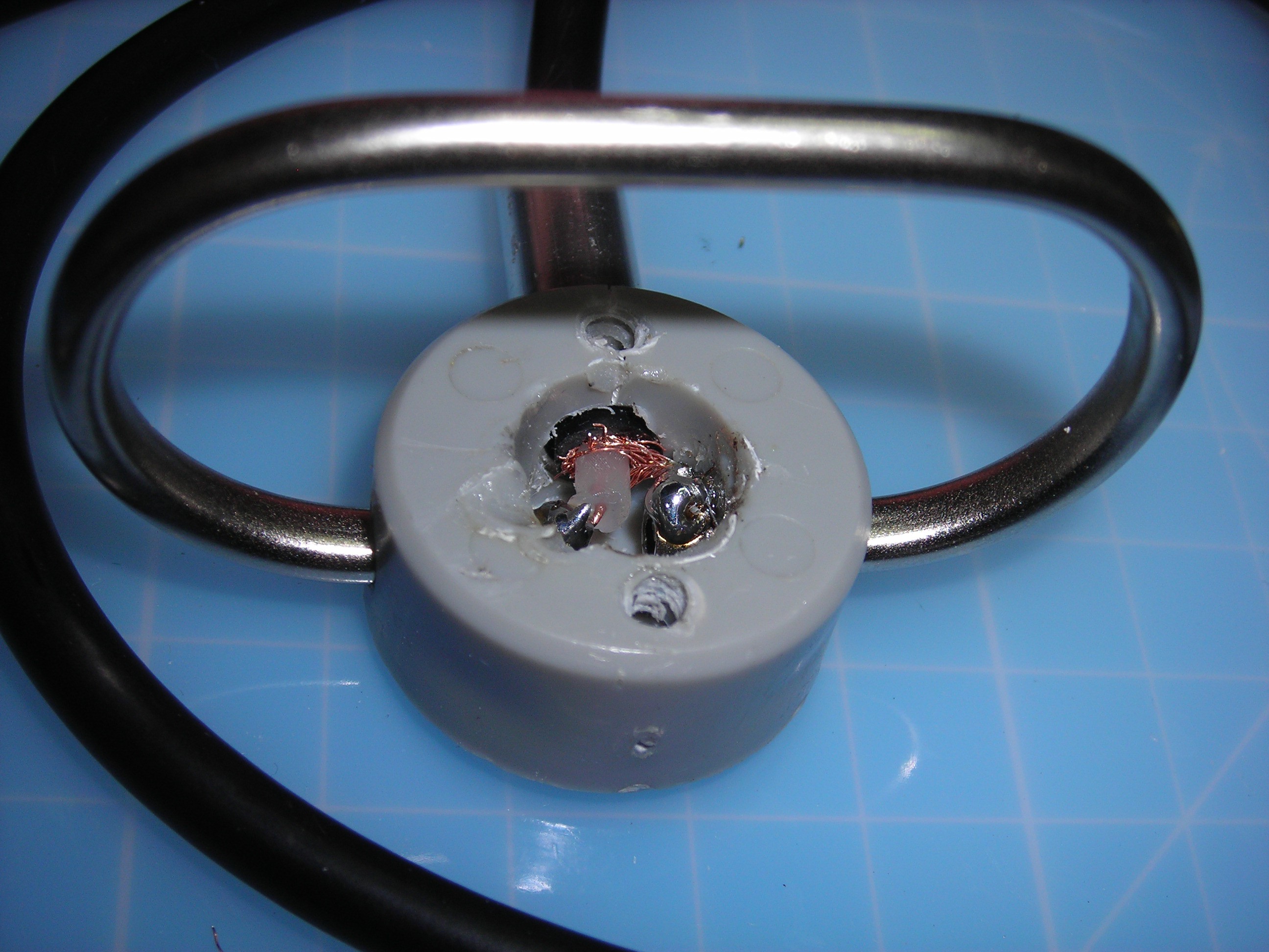
Next I disassembled the antenna / pulled off the active antenna element (you can actually "wiggle" it off to the front of the antenna - when fixing the first antenna I unnecessarily removed the reflector rod and mounting plate at the back to get access).
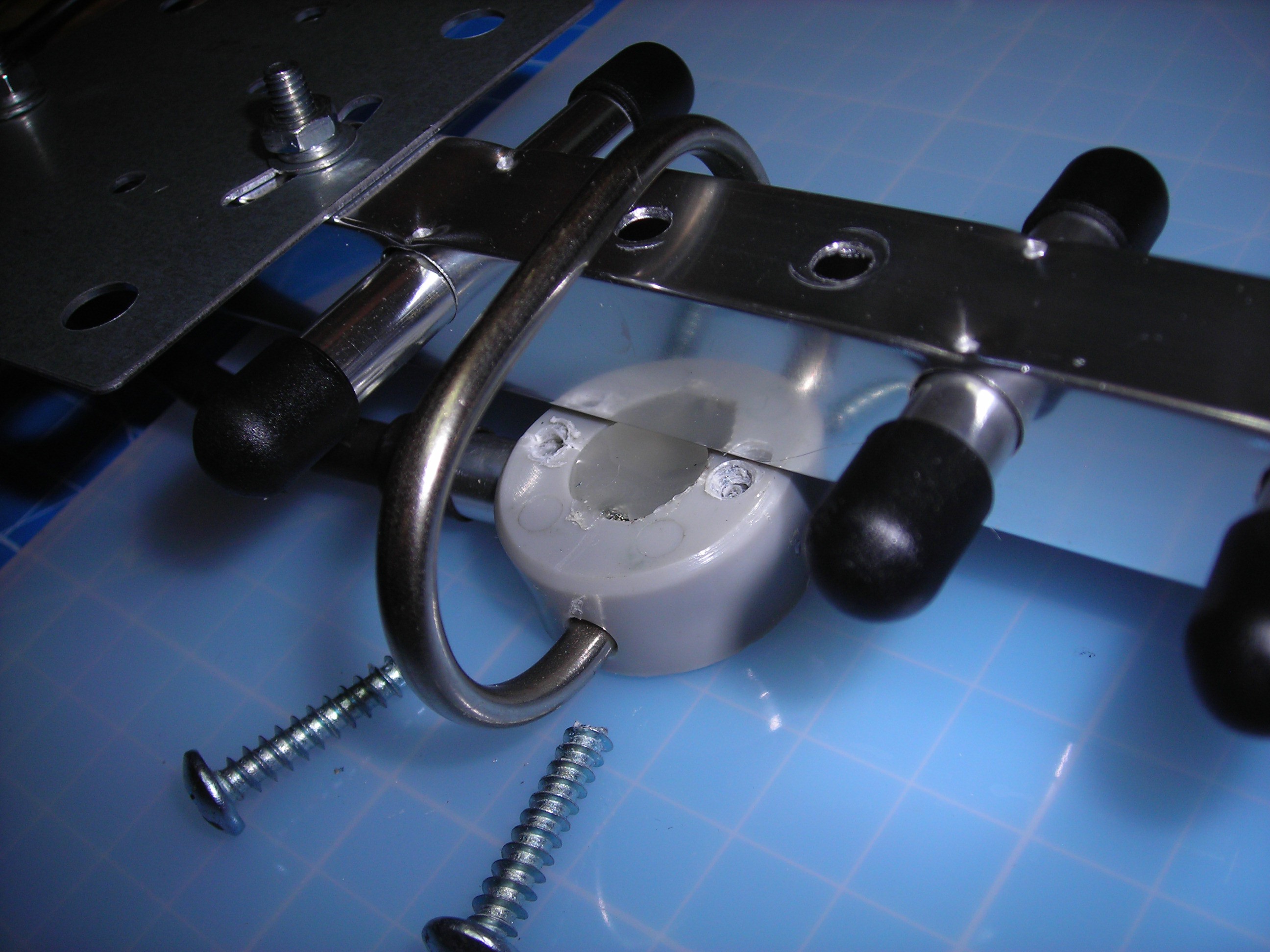
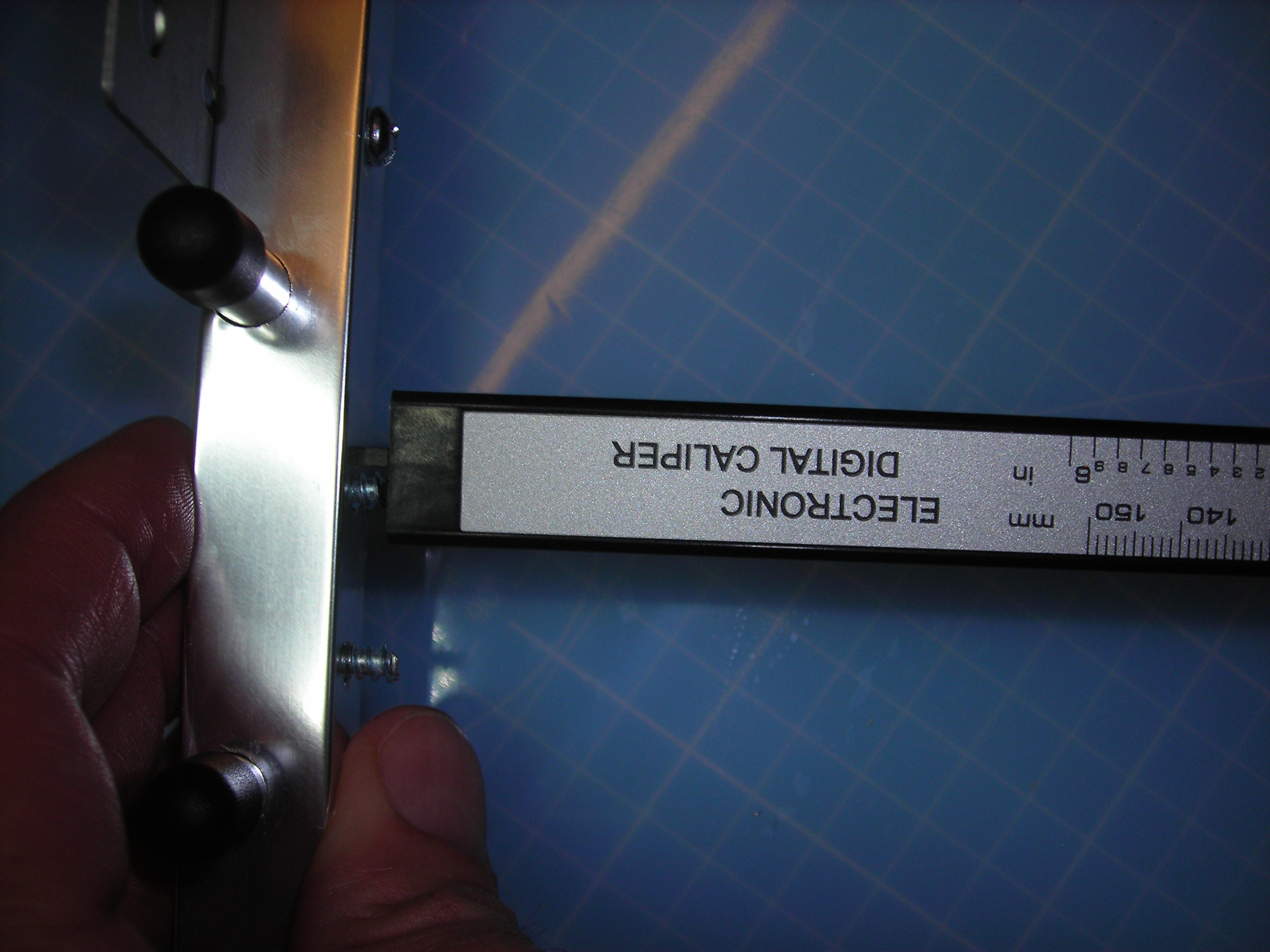
As I suspected (because of the location and length of the mounting screws) there was continuity between the metal sleeve / 'cable gland' of the active antenna element and the mounting screw towards the back end of the antenna.
Somewhat like the 'long screw damage' on Apple products... This screw was ~0.7mm too long.
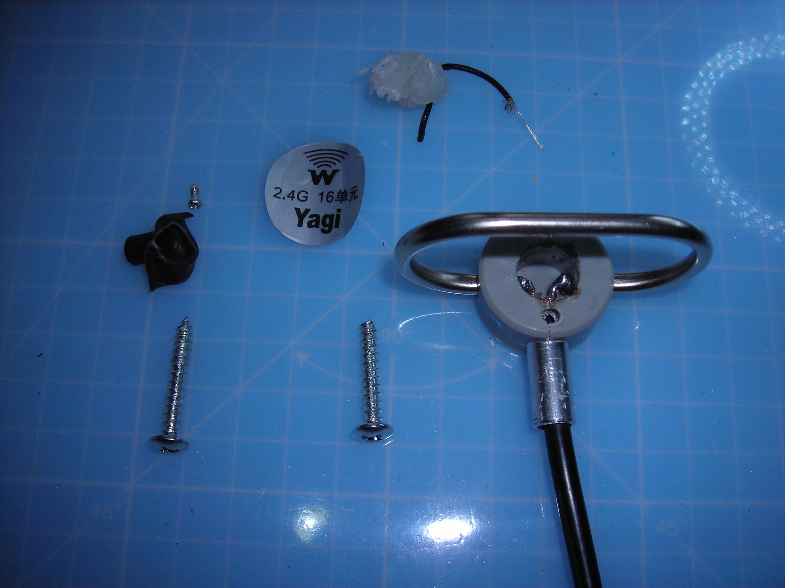
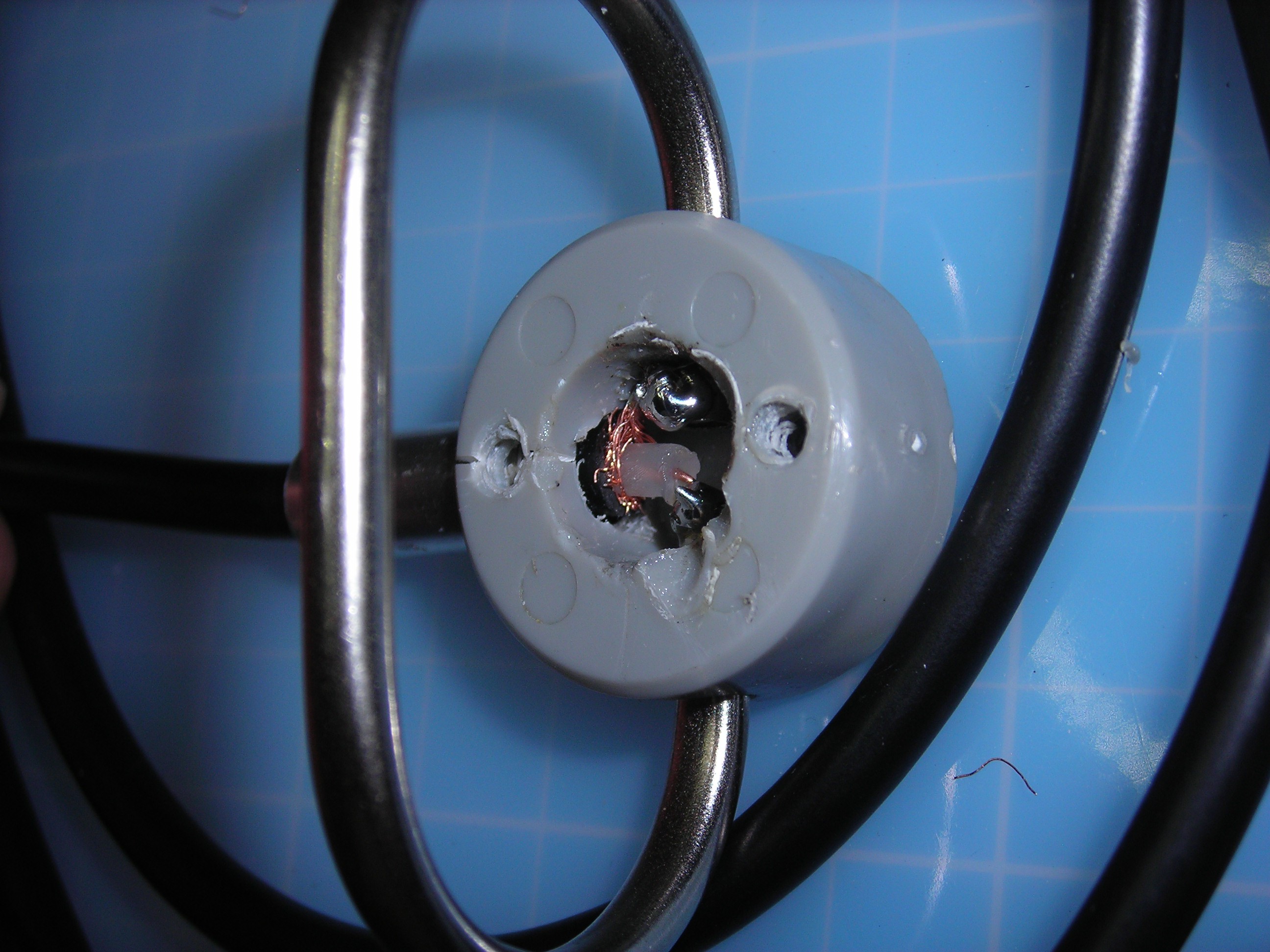
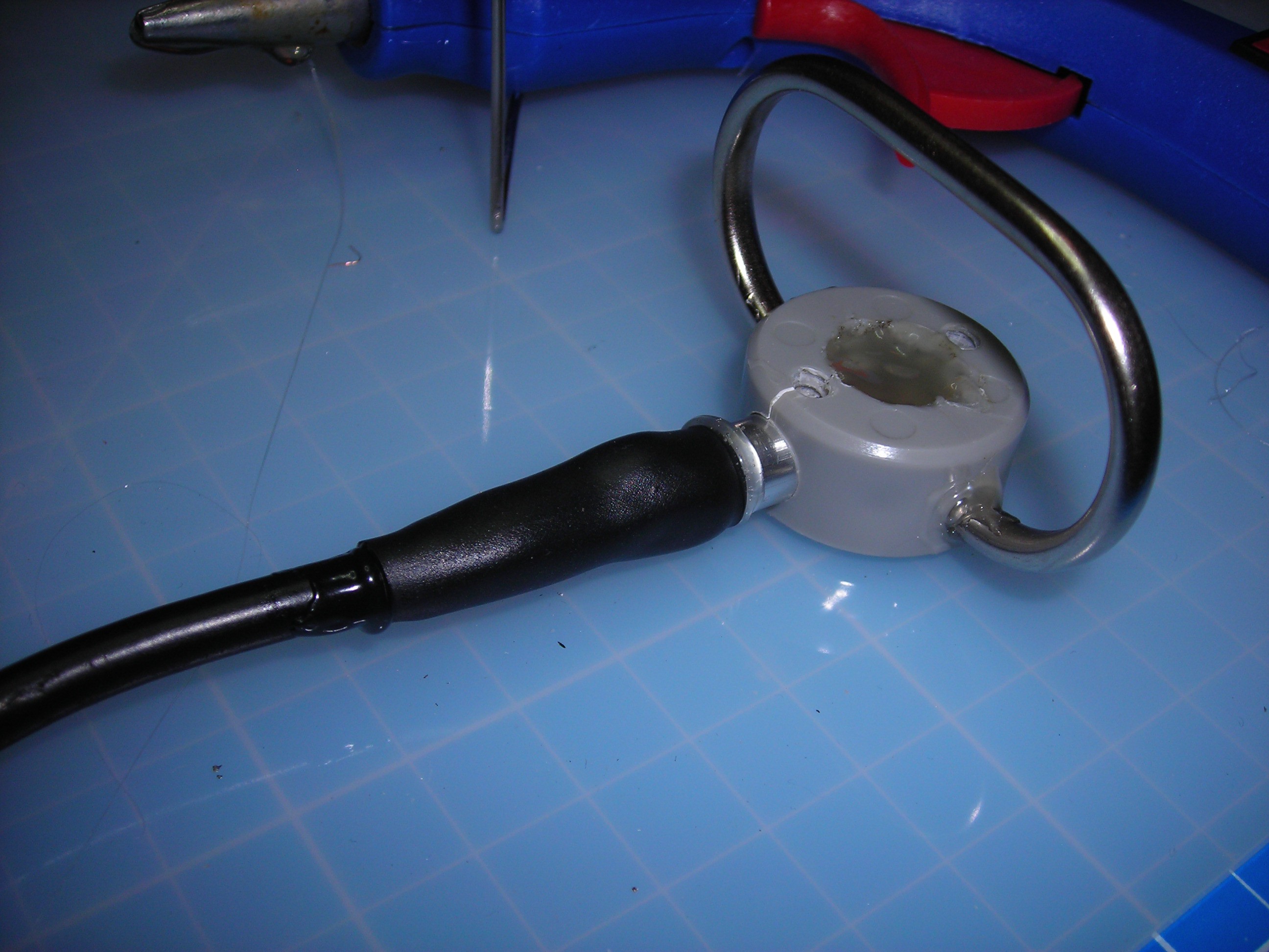
Next I removed the hot glue used to 'seal' the active antenna element and found a piece of black wire embedded in the hot glue. On the first antenna the wire was actually soldered in as a bridge (!) between both ends of the folded dipole, on the second antenna one end of the wire seemed to be loose.
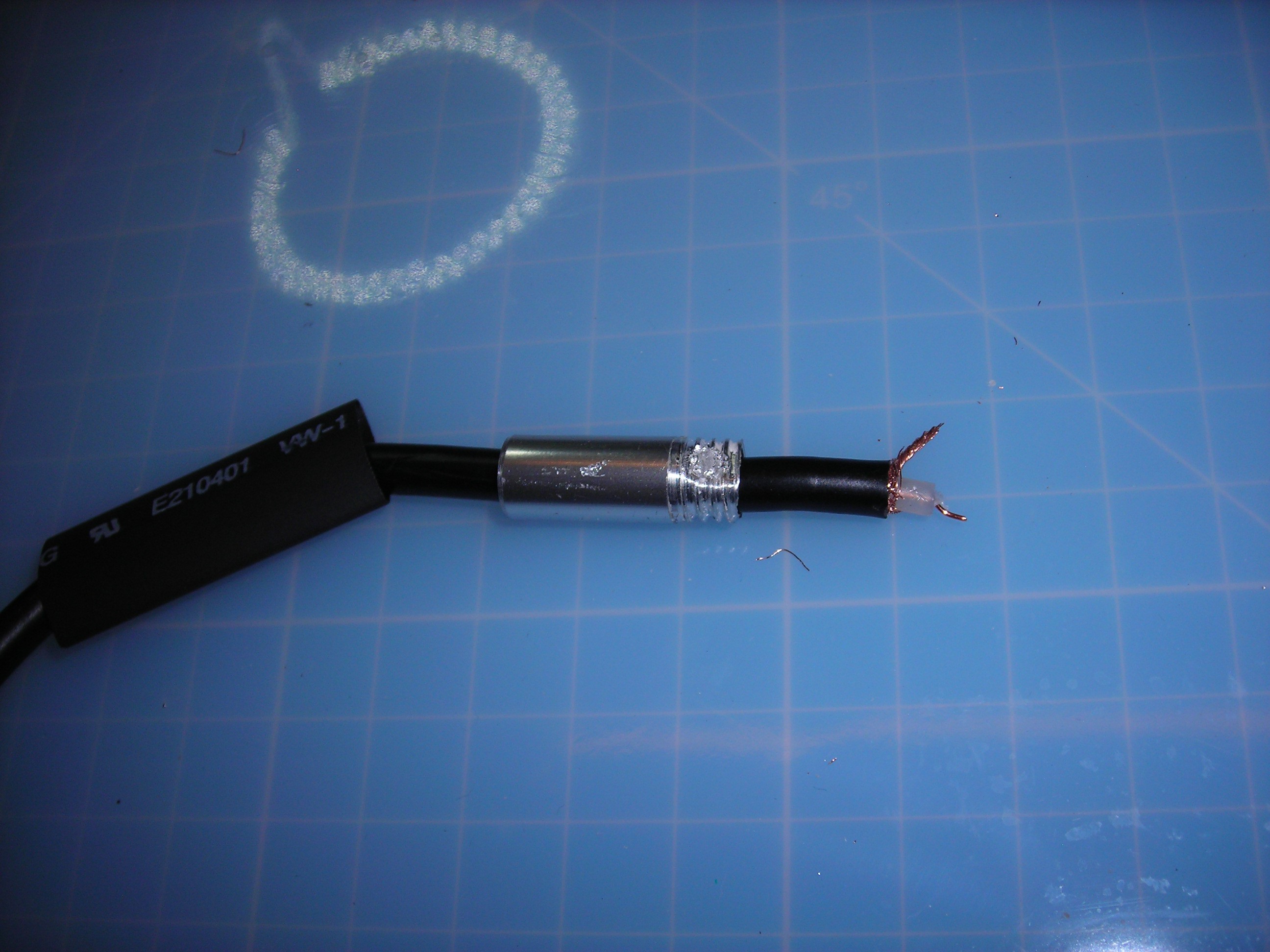
In the picture above one can already see that the stripped parts of the coax are both dangerously close to the metal sleeve. On to desoldering the coax...
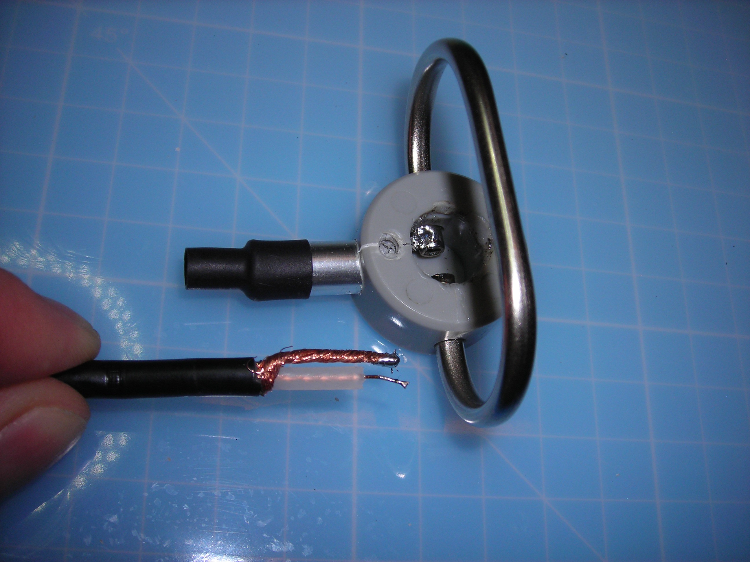
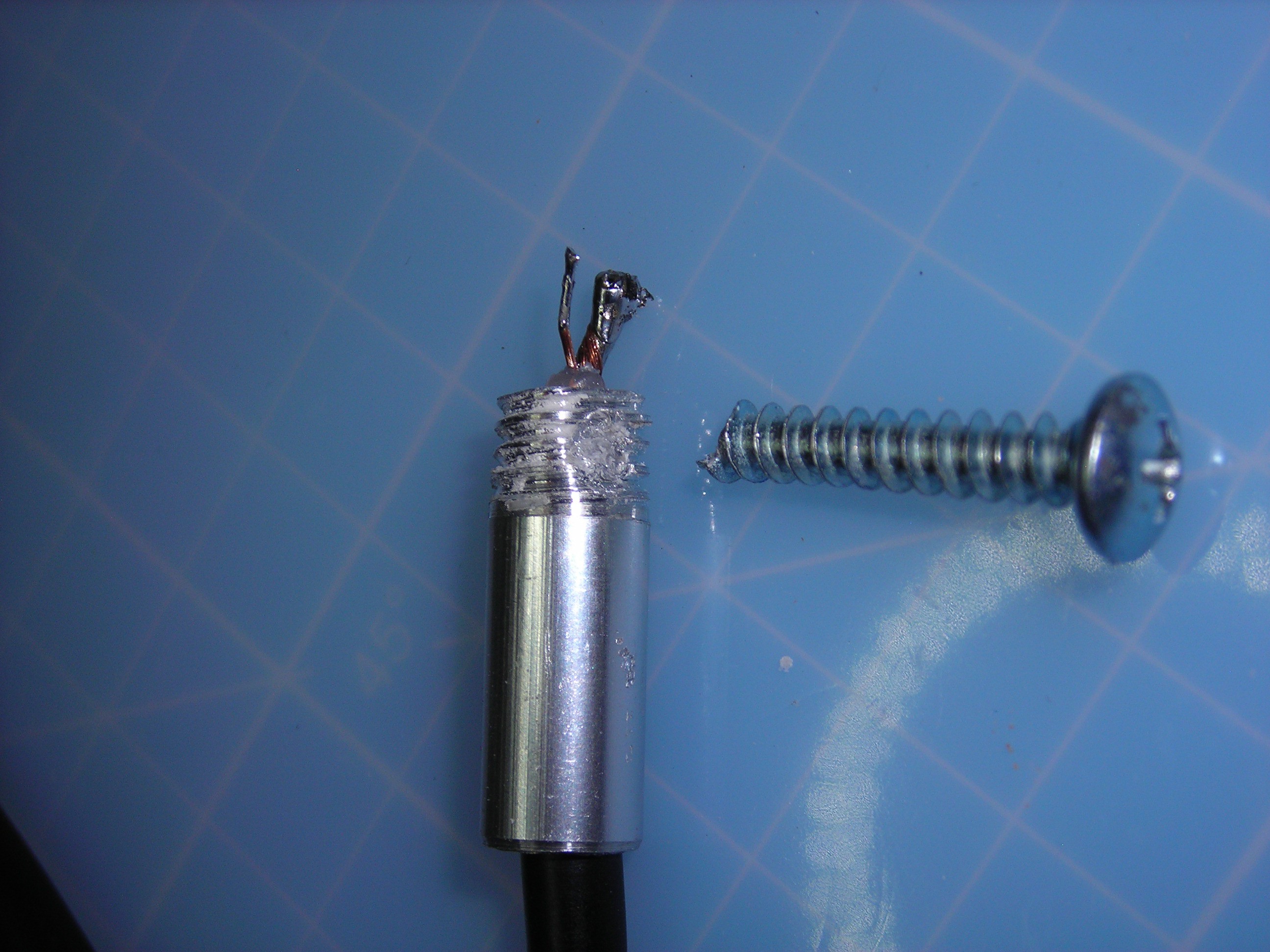
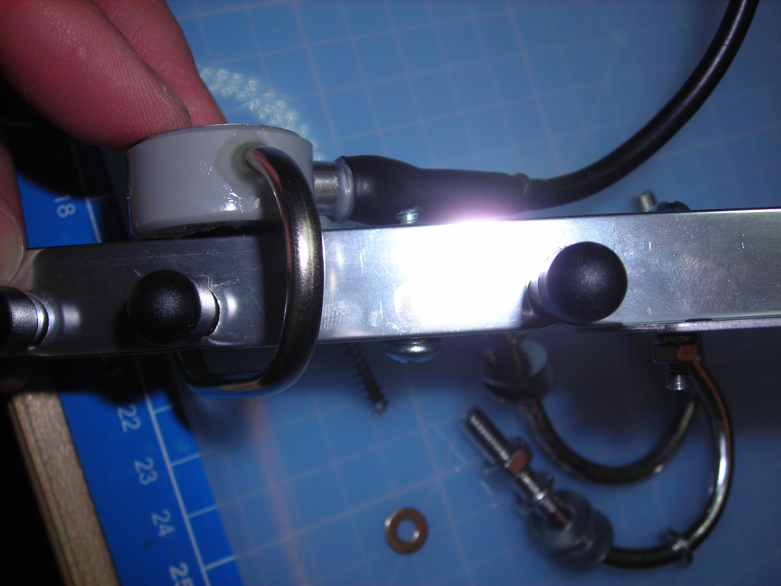
... and now the problem becomes clearly visible. The cable end is stripped unnecessarily long, the shielding braid touches the cable sleeve and the mounting screw makes contact to the whole antenna frame.
On the first antenna, the screw was longer, actually punched a hole in the sleeve and shorted the coax inside (as you can barely see in this picture).
----------------------------------------------------------------------------------------------------------------------
The 'Fix'
Fixing this to get at least a working 'folded dipole' Yagi without short circuit seems rather straightforward, the only slight problem is the accessibility of the antenna ends inside the plastic housing for re-soldering.
First the stripping of the coax is reduced to a minimum to avoid any contact between shielding braid and metal sleeve (which also should greatly benefit the signal quality according to people who - unlike me - know their stuff regarding antenna and HF-technology).
The cable ends should of course be pre-tinned before being reinserted into the plastic antenna body and the sleeve must not be forgotten - the heatshrink tube can be added later, it fits over the RP-SMA plug on the other end of the cable...
There might still be continuity to the metal sleeve if there are some 'stray' wire strands from the shielding bent back inside the housing, so now is the time to test this again and - if necessary - pick out unwanted wire strands with tweezers or something...
Now to reseal everything with hot glue again. I suppose you can also use epoxy for a more watertight seal, but for my purposes hot glue is totally OK. The rest of the antenna doesn't really look long time outdoor-safe for european environmental conditions anyway....
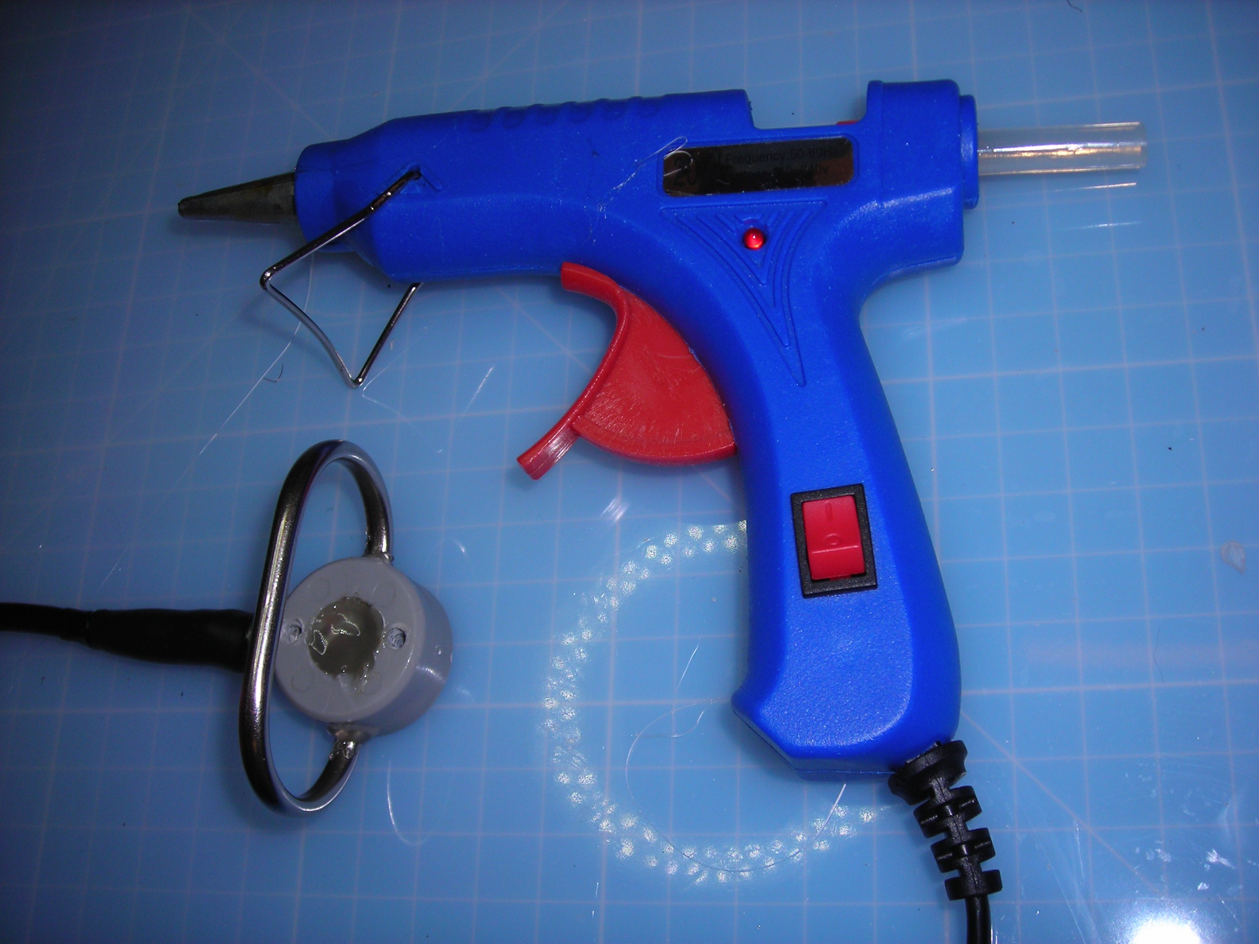
For the 'cable gland' I used a shrink tube and hot glue + hot air to get a relatively tight seal.
Because the antenna is intended to be mounted vertically, I also sealed the openings between antenna loop and plastic housing with some hot glue and spread / smoothened the glue with a hot air soldering station for a better "finish".
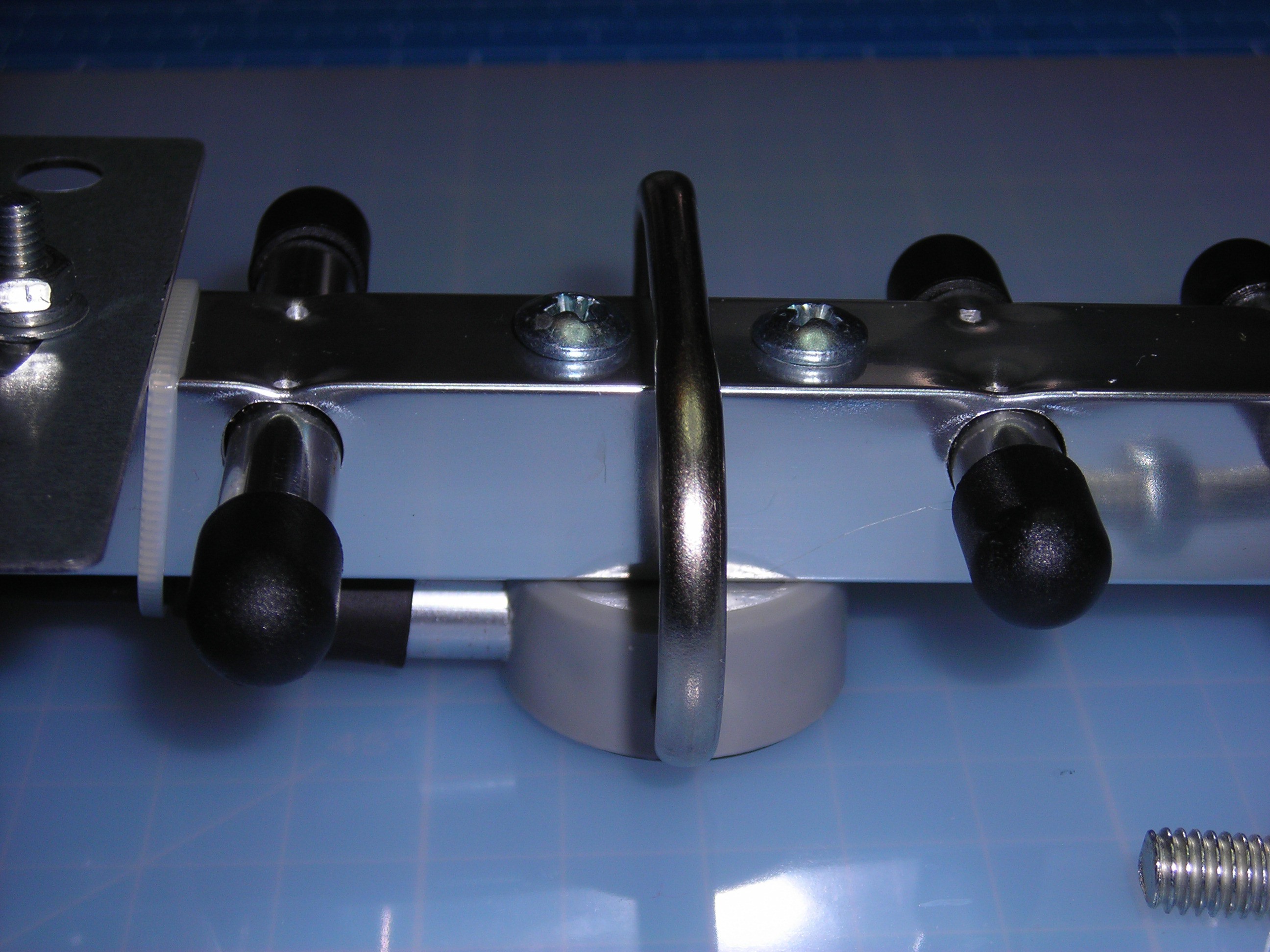
Additionally, washers were put on the offending mounting screw to reduce the possibility of overtightening it and breaking the metal sleeve.
On the first antenna, I had shortened this screw with a hacksaw because it was MUCH too long, but here it's only 0.7mm and I didn't want to bother with filing off the screw end and perhaps ruining the already bad thread start.
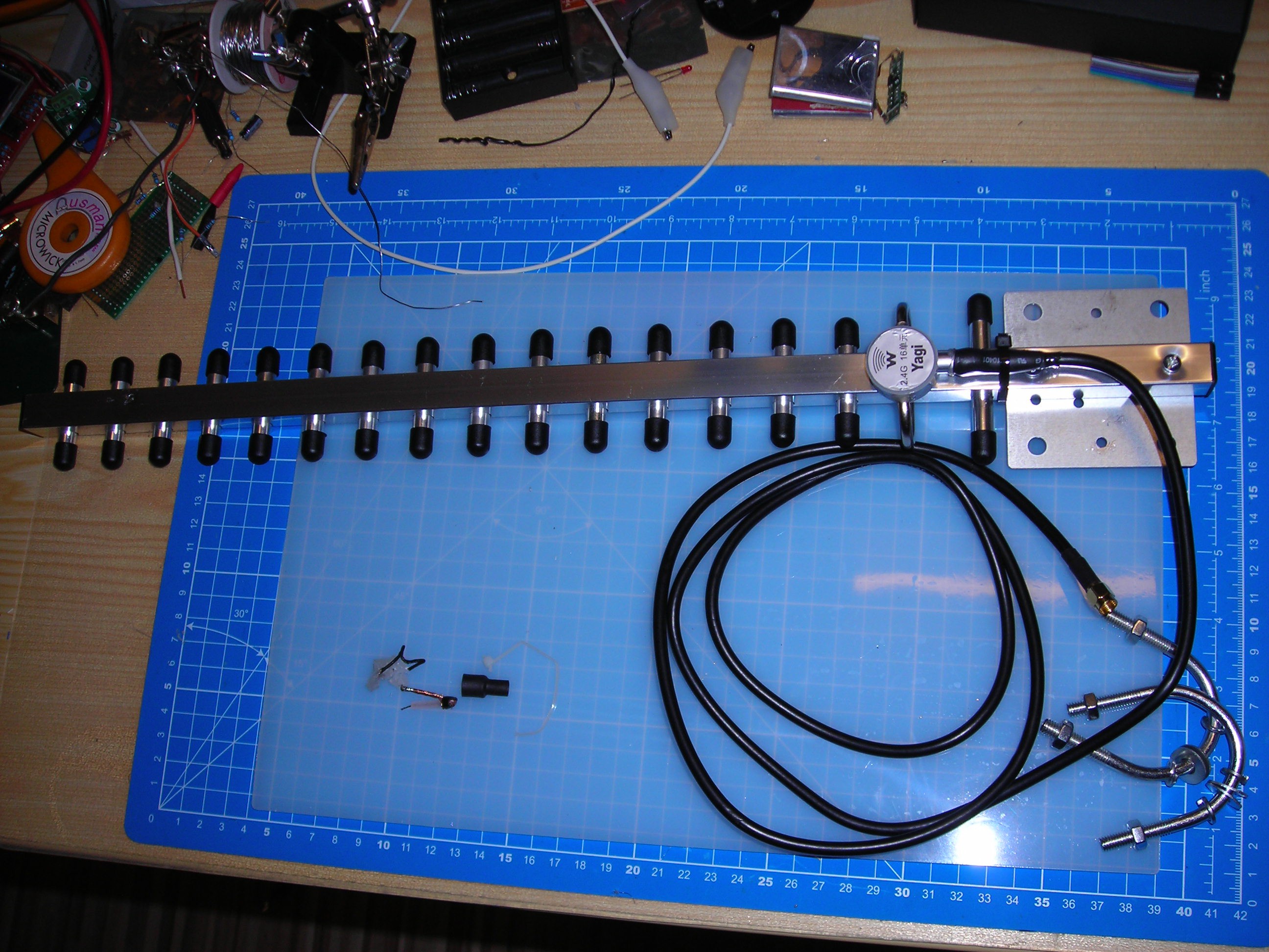
Finally I put everything back together again (old/removed parts on the bottom left):
and.....
SUCCESS: from hardly one Access Point to six just laying on the desk in my basement.
Directionality was also restored / enabled and the antenna was already used successfully to provide WiFi in the garden two days ago (just mounted on a tripod next to the router indoors and pointed in the general direction of the BBQ place outside - this place is normally JUST out of range for usable WiFi).
On a distance of about 20m we got a circa 6m wide cone of "Smart Phone usable WiFi" to the delight of my guests. People today don't seem to get by without Spotify and WhatsApp any more, even if there is enough beer and steaks for everyone...
It would be interesting to know how many of the similar antennas out there exhibit the same problems, so I hope this helps people check out their antenna when in doubt regarding missing directionality or shorted out antenna body.
Discussions
Become a Hackaday.io Member
Create an account to leave a comment. Already have an account? Log In.
Oh man, this is such a great guide. I followed everything to a T but I still unfortunately was unable to send wifi to another building. The stock antenna on my Netgear WNDR 3400 v1 provides better reception than this antenna even after I attempted to fix it. It could be:
1) my terrible soldering skills
2) the antenna adapter I used for the WNDR 3400 not lending itself to use the Yagi antenna
3) maybe there is something else wrong with my eBay Yagi?
Are you sure? yes | no
Very nice
Are you sure? yes | no
No I'm referring to this quote from the OP:
"and found a piece of black wire embedded in the hot glue. On the first antenna the wire was actually soldered in as a bridge (!) between both ends of the folded dipole"
Now I wonder why someone may have soldered a piece of wire in there?
Are you sure? yes | no
If you aim for best antenna performance it's worthy to apply some impedance matching solution of the following: http://dg7ybn.de/Phasing/Phasing.htm as Yagi have impedance of 240-300 ohm, while coax cable is 50-75 ohm impedance.
Are you sure? yes | no
The impedance matching was in there but he totally disregarded it.
Are you sure? yes | no
@SunRay more please. Do you mean this ? http://dg7ybn.de/Phasing/Pics/50ohms_200ohms_corr.gif
Are you sure? yes | no