Close
0%
0%

Kilonomicon

A kinetic sculpture made from 1024 relays.

Public Chat
Similar projects worth following
I make kinetic sculpture (one piece, El Jefe de M&Ms (an M&M sorter) has even been featured on Hackaday). I'm currently designing a piece as part of my series of relay-based sculptures that I call Metronomicons. Since this piece will contain 1024 relays, I'm tentatively calling it, "Kilonomicon."

Kilonomicon will have at least two modes of operation.  In one, it will play brief patterns of sounds on a subset of the relays (anywhere from one to, say, 100), separated by random intervals of several seconds up to a couple of  minutes.  In the other, it will play a three to four minute composition that will enlist all the relays (at least for some sections).  The first mode will be the default, with the second kicking in every hour or so.

There may be an additional mode allowing one or more people to "play" Kilonomicon in real time via some sort of MIDI interface.  I'm hoping to at least partially fund Kilonomicon through Kickstarter, in which case this additional mode will be a stretch goal.  Another stretch goal may be to commission actual composers to create the mode 2 piece(s), though I've already located a couple of composers willing to give it a shot for free due to the novelty of Kilonomicon. 

I hope to display Kilonomicon at music festivals (e.g. Coachella, Lollapalooza, Electric Daisy Carnival, etc.) and science museums around the country (or world, if someone funds the travel) for a year or two, and then find a permanent home for it.

Given it will be moved around a lot, I've decided a modular structure will be the best approach.  While this will require assembly and disassembly, it makes crating and shipping much easier than it would be for a monolithic piece measuring roughly 10' tall by 10' wide by 6' deep (that tipsy woman in the render is 5'9" tall).  It also makes initial construction much easier since I can build the modules at my leisure and then rent a space for a few days to do the final assembly for testing.

The architecture consists of 64 electrically identical modules, each containing 16 24VDC relays in a 4x4 array with .5" spacing, and a controller board (based on an Atmel (Microchip?) ATMega32A).  These modules will be assembled in an 8x8 array.  Mechanically, the inner 36 will be identical (12"x12"x.5"), but the 28 forming the perimeter will be sized differently to provide the border you see in the render.  The modules will be networked together via RS485 and controlled by a single master controller board which will read relay configurations from on-chip flash and an SD card and spit them out onto the bus as 4-byte packets (1 start byte + 1 address byte for the associated module + 2 configuration bytes (16 relays = 16 bits = 2 bytes)).  

Each relay draws 83 mA, leading to a total system power draw (including power supply efficiency) of 2.7kW.  This will be divided among eight switching power supplies.  Here's a sketch:
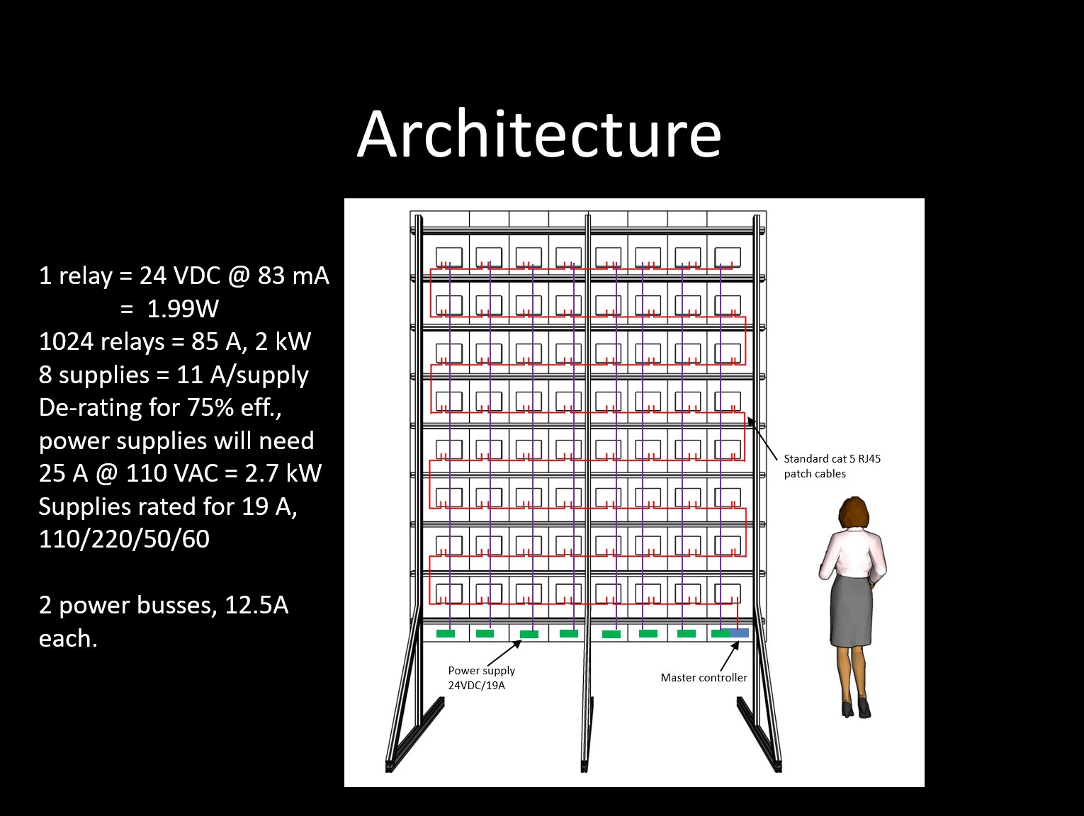
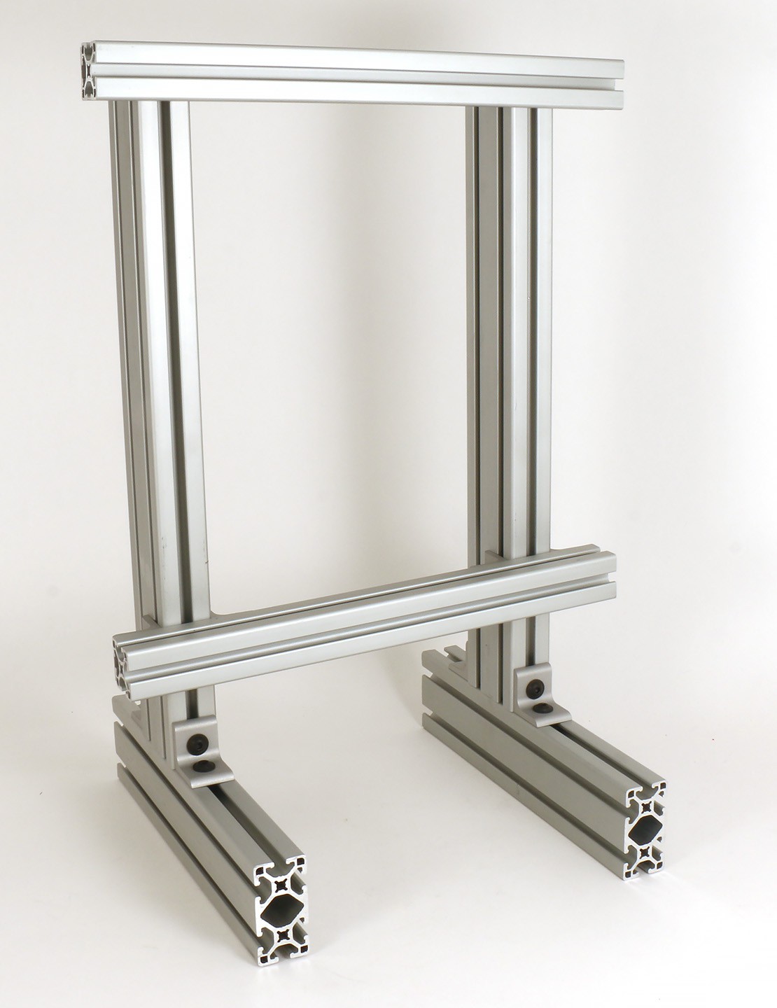
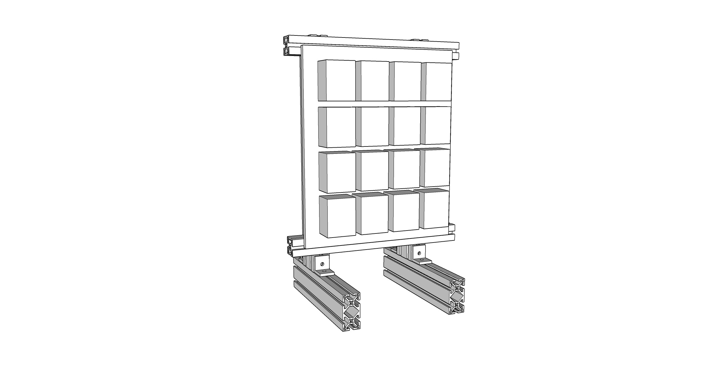
The frame will be made from 80/20 extrusions.  The design is still being fine-tuned (e.g. the joint between the three legs and three horizontal "feet" needs to be reinforced).  I intend to perform wind force analysis to determine how strong a gust it can withstand before being blown over.

I'm on version 2 of the PCB design for the module controller which I'm about to release to the fab in China.  I've evaluated several Chinese relay suppliers and settled on one; I've build one module out of 16 of their relays..  

The relay control signals will be fed from the module controller via two RJ45 cables (each containing eight conductors).  Due to their massive use everywhere, these are cheap, reliable, easy to find, and available in a wide variety of lengths and colors.  Since they already have connectors on the ends, I won't have to make my own cables.  In fact, I can take a single, say, 2' cable, cut it in half, and have the two cables I need for one module.  All I have to do is strip the ends of the exposed wires.  The RS485 network will also run over RJ45 cables (though these will be shielded).

My plan is to build a single module and use one of the module control boards to control it and another to...

Read more »

  • Finally, back to work

    Involute10/02/2018 at 23:54 0 comments

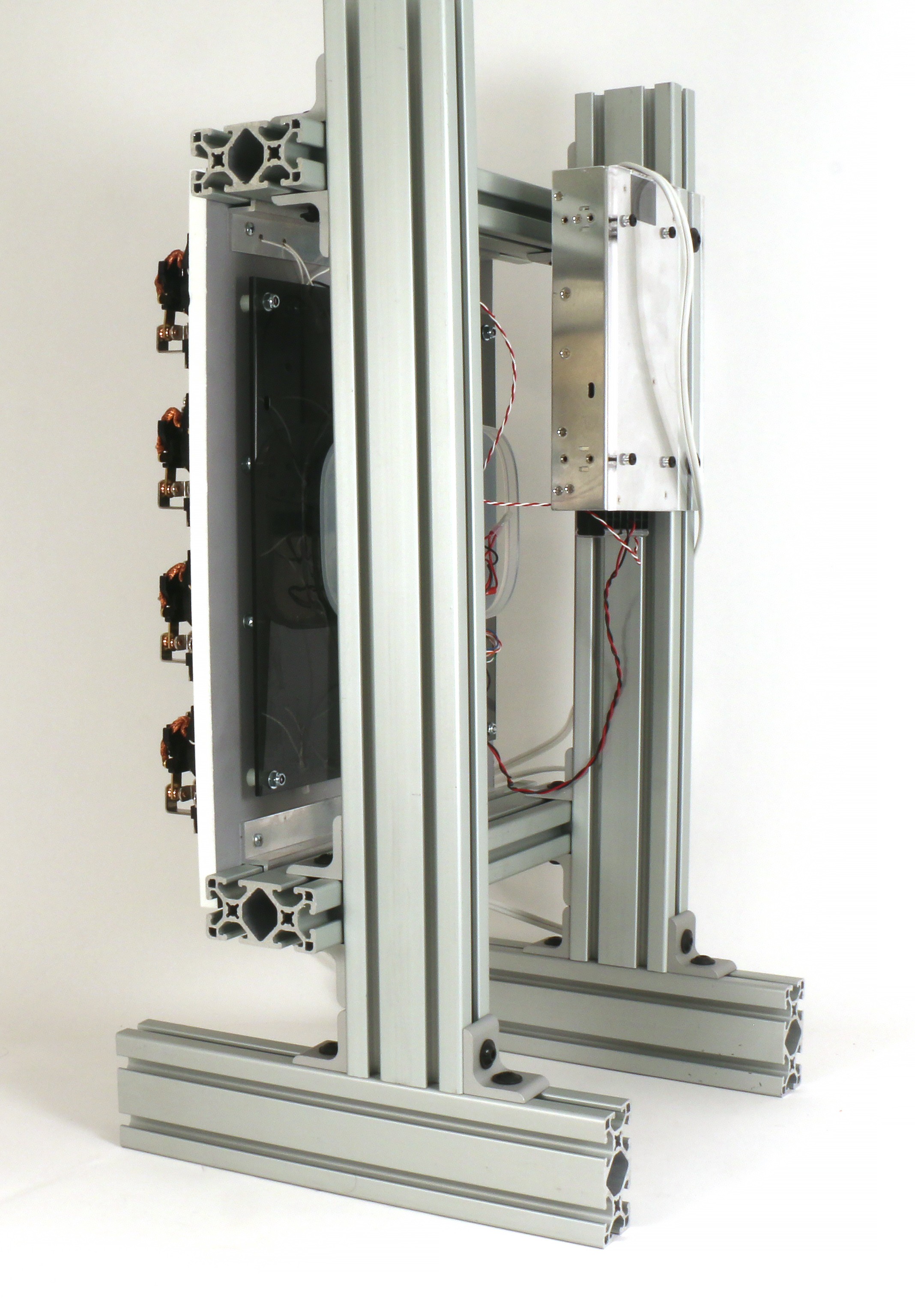
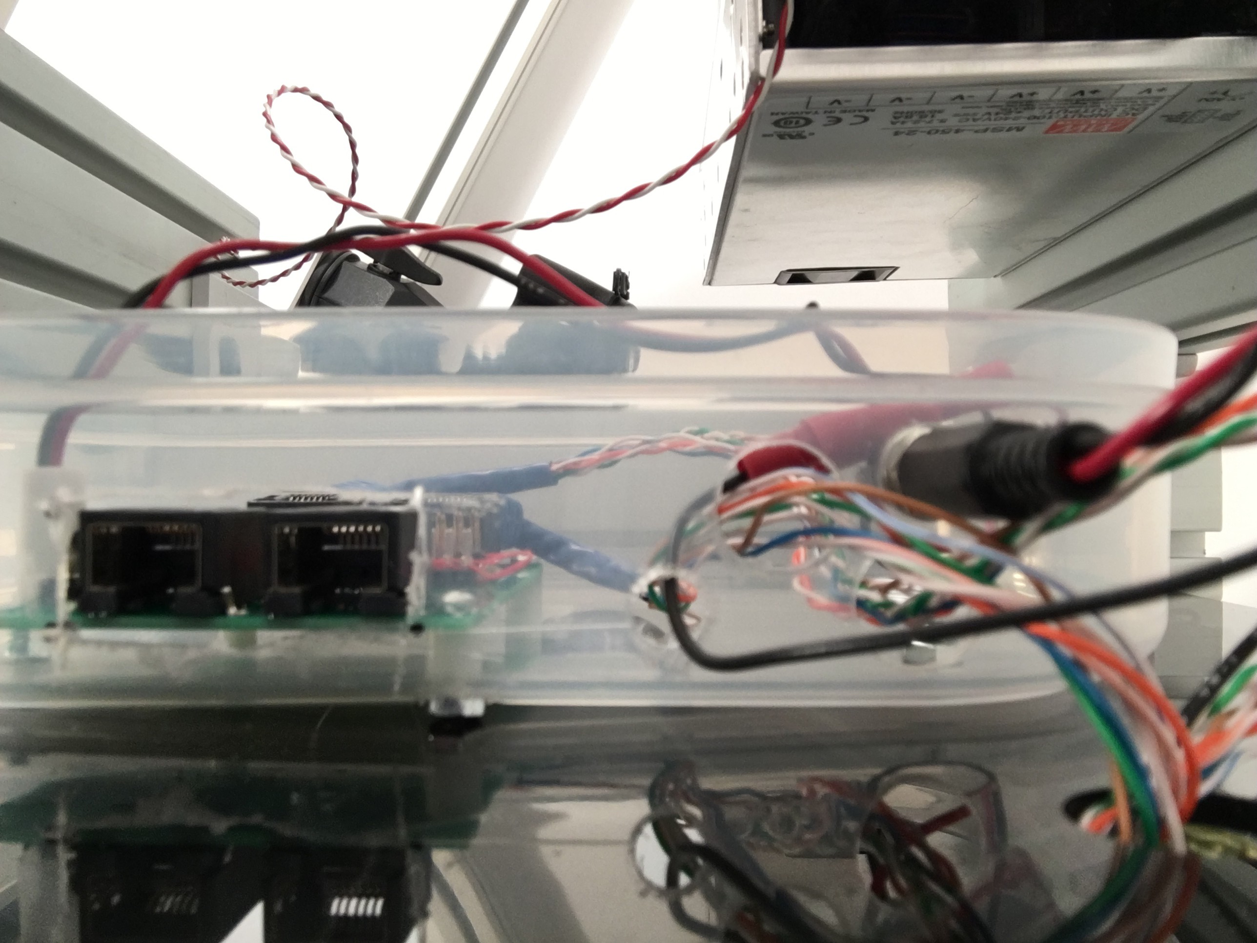
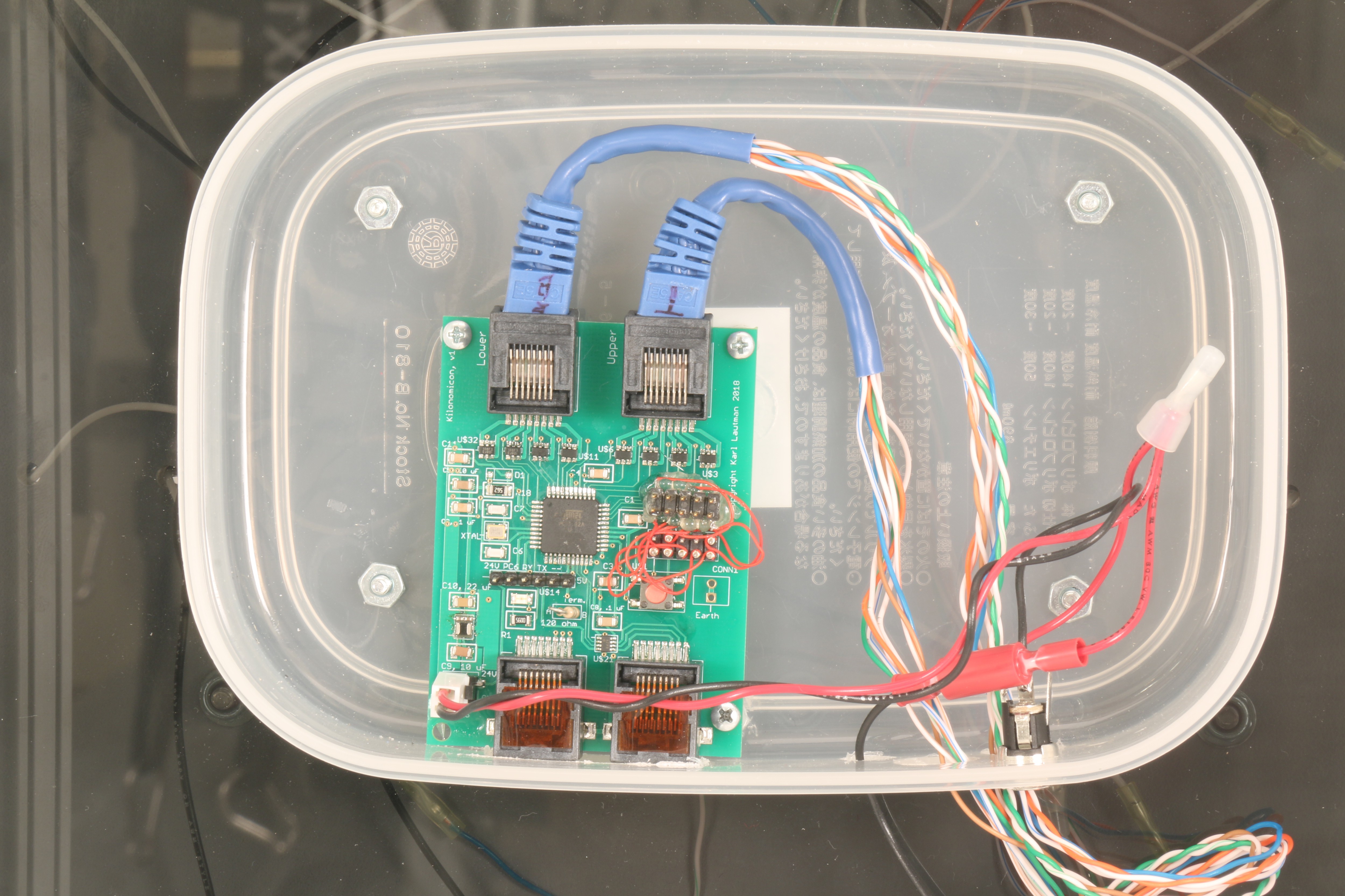
    Well, summer, life, and various project setbacks have delayed log entries here, though much progress has been made, too.  After assembling the relays on the panel, I attached the small Tupperware box containing the PCB (to protect it, at least partially, from the elements and curios fingers when on display) to the back, only to realize that I could no longer slide the panel back onto the frame; the box collides with the uprights.  So, I replaced the 1.5" x 1.5" horizontal supports with 1.5" x 3" ones (the same profile I'm using for the uprights and feet), and now there's plenty of room:

    The power supply in the upper-right is an example of the actual one I plan to use in the finished piece (well, x8).  The piece of smoked acrylic filling most of the rear of the panel protects all the wires running from the box to the relays; with frequent assembly and disassembly, it would be easy for them to get caught on something.  The acrylic also hides them, resulting in a much cleaner look from the rear.  I think I'll use white acrylic in the final piece, though.

    So, you'd think with a complete mechanical assembly, PCB, and power supply this thing should be ready to rumble.  And, you'd be right:

    Keep in mind this was just a test to see if everything was connected (and properly), and to see what sorts of sounds and frequencies I can get out of a panel.  Still, multiply it by 64 and at least you've got quite a racket.  Hopefully, the composers associated with this project will be able to make it a pleasant, or at least,  entertaining racket.

    Naturally, on the heals of my success I blew up the PCB by shorting the Vcc and ground rails together while measuring voltage under the load of operation.  I reflowed another one (remember, I have 10 ;-) ) and made a note to put the test pins for Vcc and ground farther apart on v2 of the PCB (they were adjacent on the test header of v1).  

    I also decided my original idea of just drilling two or three holes in the side of the box to feed wires to the PCB wasn't going to cut it at scale.

    Even though I could make them cleaner, I'm seriously considering bringing the piece to Burning Man and the dust on the playa is like talcum powder and gets everywhere.  The RJ45 connectors (for the RS485 network) hanging out the side were just begging for infiltration.  I decided on this approach:

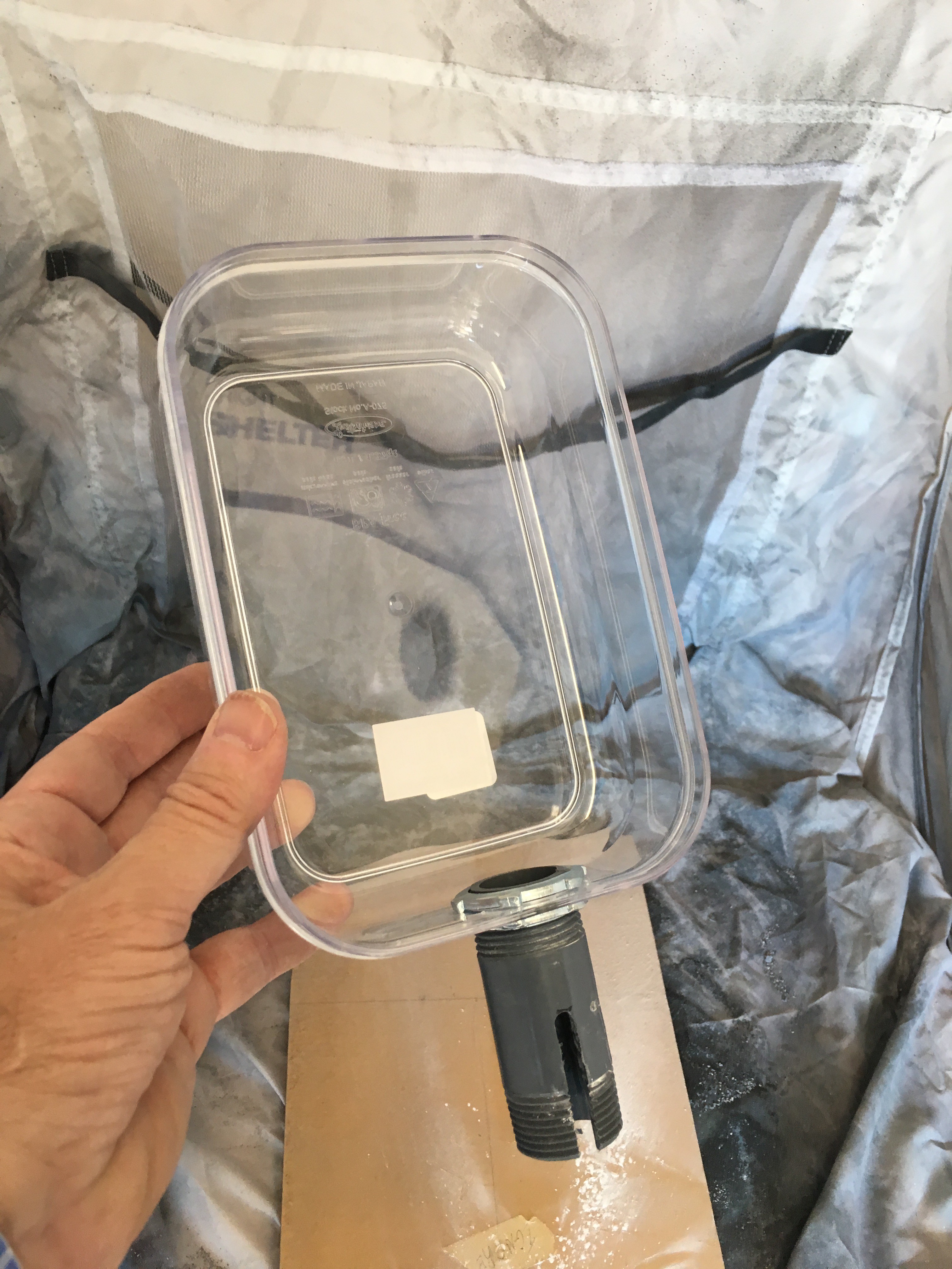
    The idea is to feed all four RJ45 cables (two for the relays and two for the network) through that gray, schedule 40 nipple (pipe) into the box, then guide them into the slot milled in the side of the nipple.  This will allow me to screw a cap on the end, creating a tight (though not air or water tight) fit.  The only question is, with the box oriented vertically on the panel, will the small gaps between the cables and pipe allow powder to be blown into the pipe and then up into the box.  

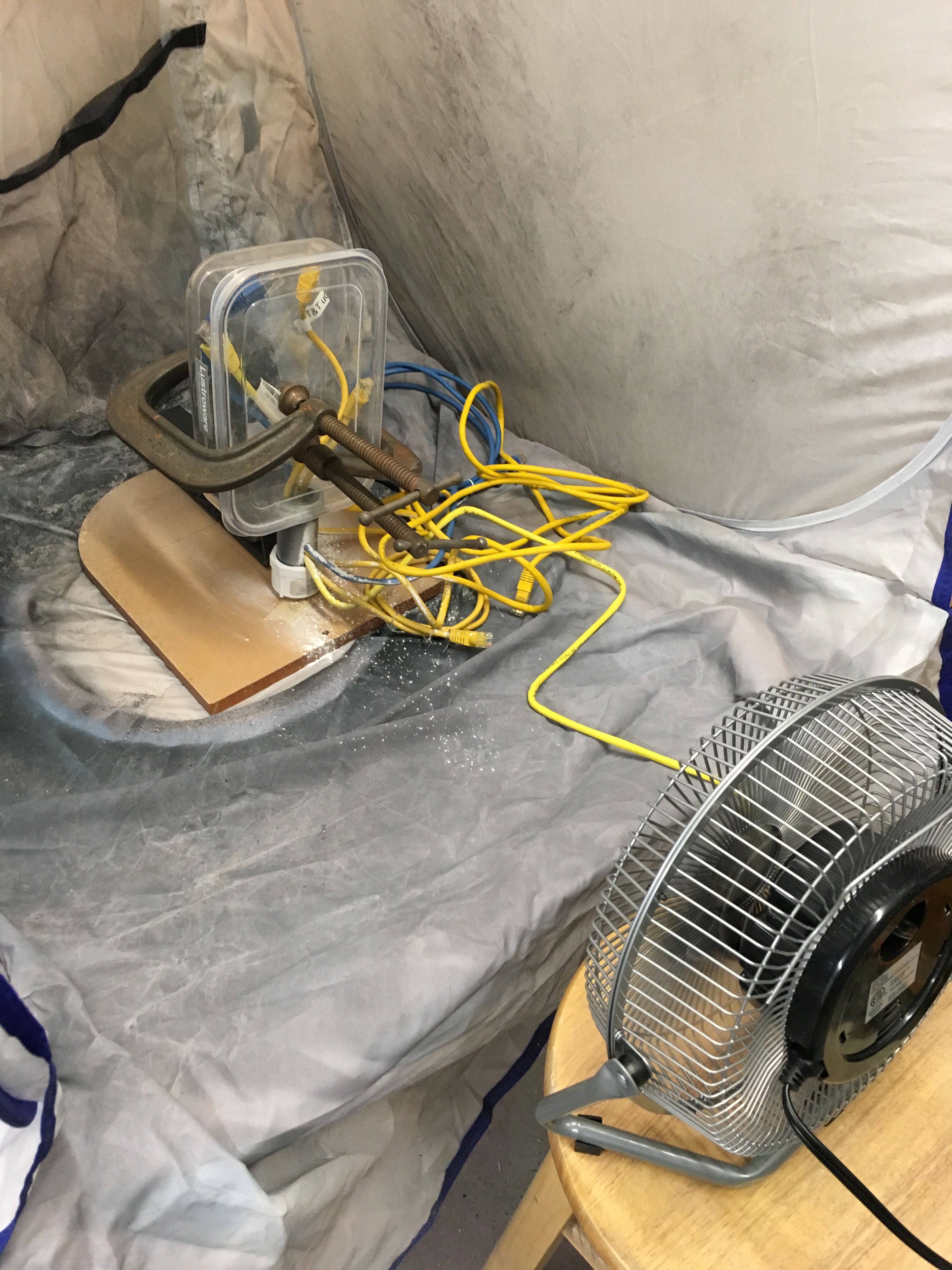
    To test it, I placed the assembly of box, pipe, and cables in my collapsible spray booth and used a desk fan to blow talcum powder at it:

    No talc made it into the box, so this is the approach I'm going with (however unscientific it may be).

    I'm also moving all the RJ45 connectors to one edge of the PCB in v2 so I don't have to bend them so sharply as with v1:

    The new board will fit in the box with the connector edge horizontal and pointing down, towards the pipe, allowing the cables to flow almost directly into their jacks.

    Other things addressed in v2 are correctly wiring the JTAG connector; a new RS485 transceiver as the initial one was end-of-lifed by Maxim as soon as I got the v1 boards from China; and, a new DC-DC converter as the tiny one I used in v1 was bridging too easily during reflow, and the bridges are hard to fix since they're under the part, so I switched to a larger, but through-hole converter that shouldn't give me any problems.

    I probably won't have anything to update until I get the v2 PCBs back, hopefully in a...

    Read more »

  • Filling out the panel

    Involute07/19/2018 at 20:21 0 comments

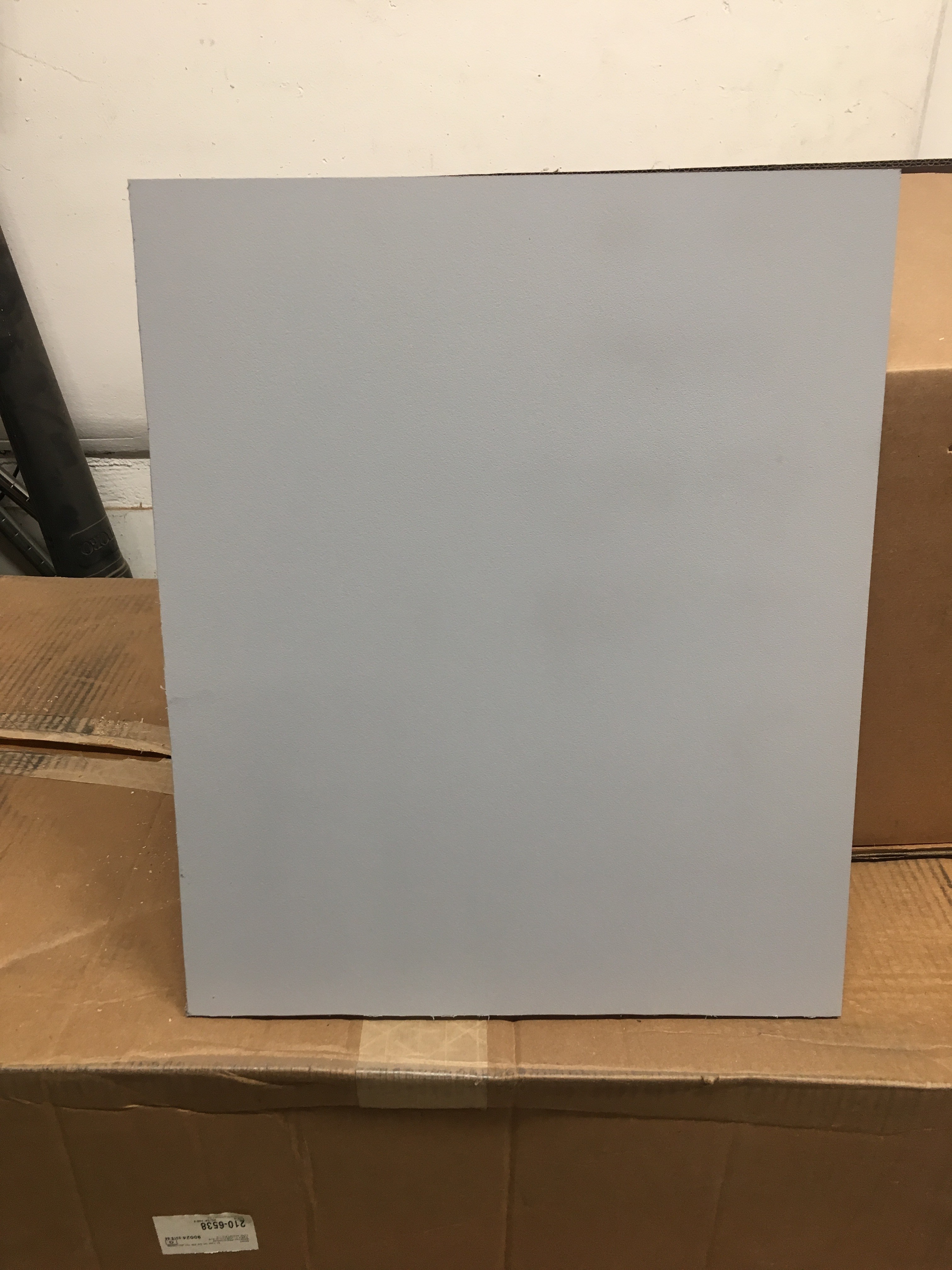
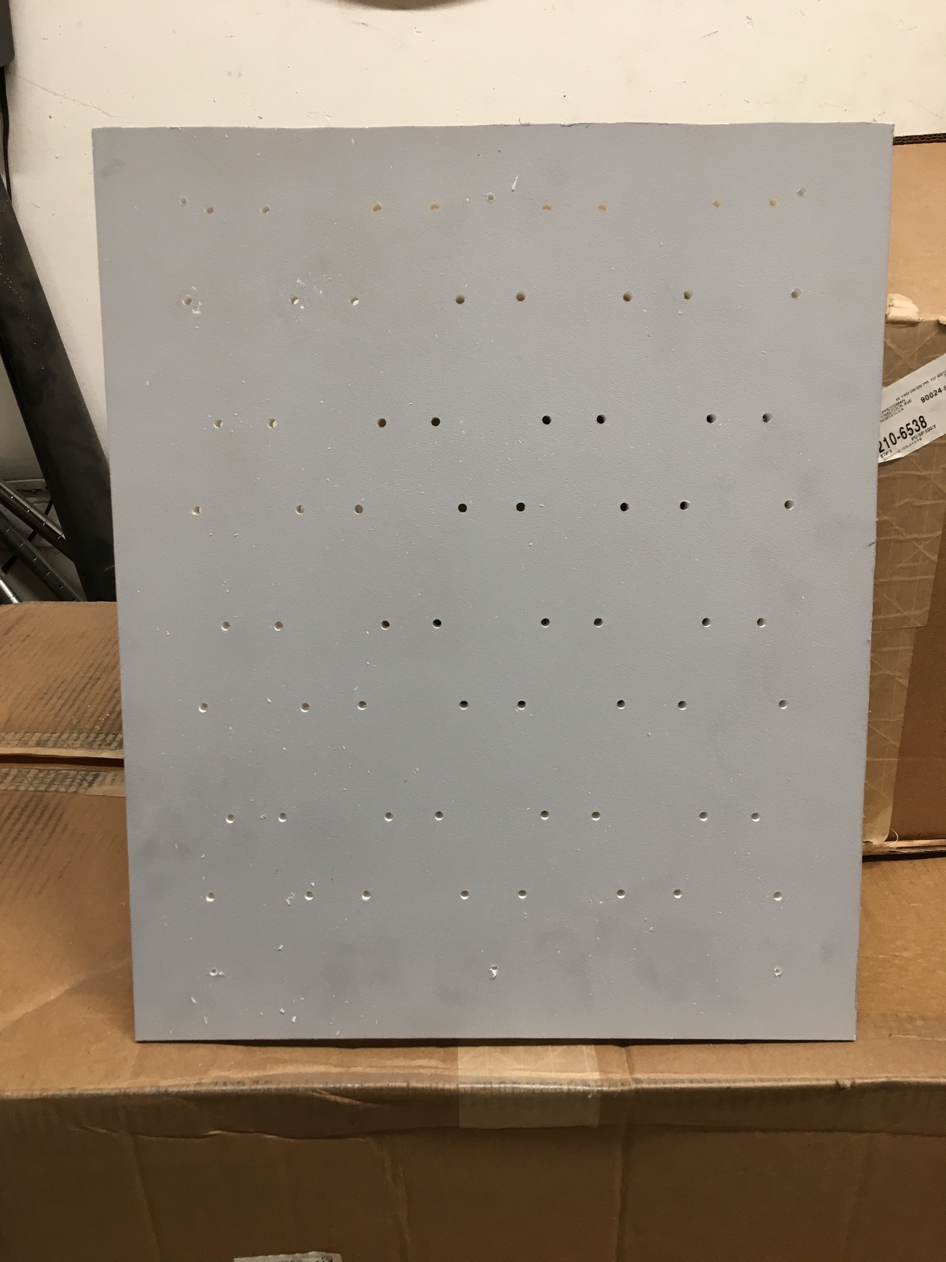
    Well, I wasn't able to etch holes in the panel without turning each one into a gooey, melted mess, regardless of laser settings.  So, I decided to hit one side of the panel with a coat of primer:

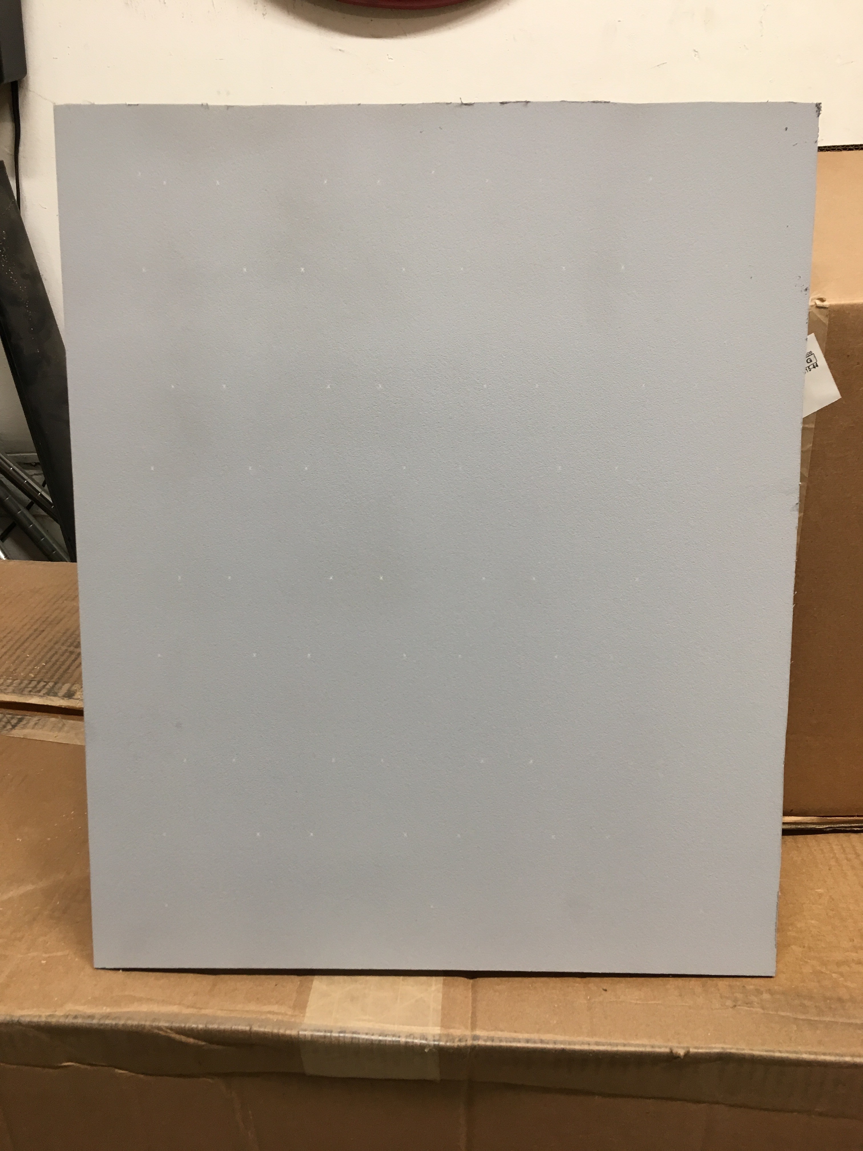
    then laser etch an "x" through the primer wherever a hole is supposed to go (barely visible in the photo):

    then center punch each "x" to provide a better guide for the drill bit:

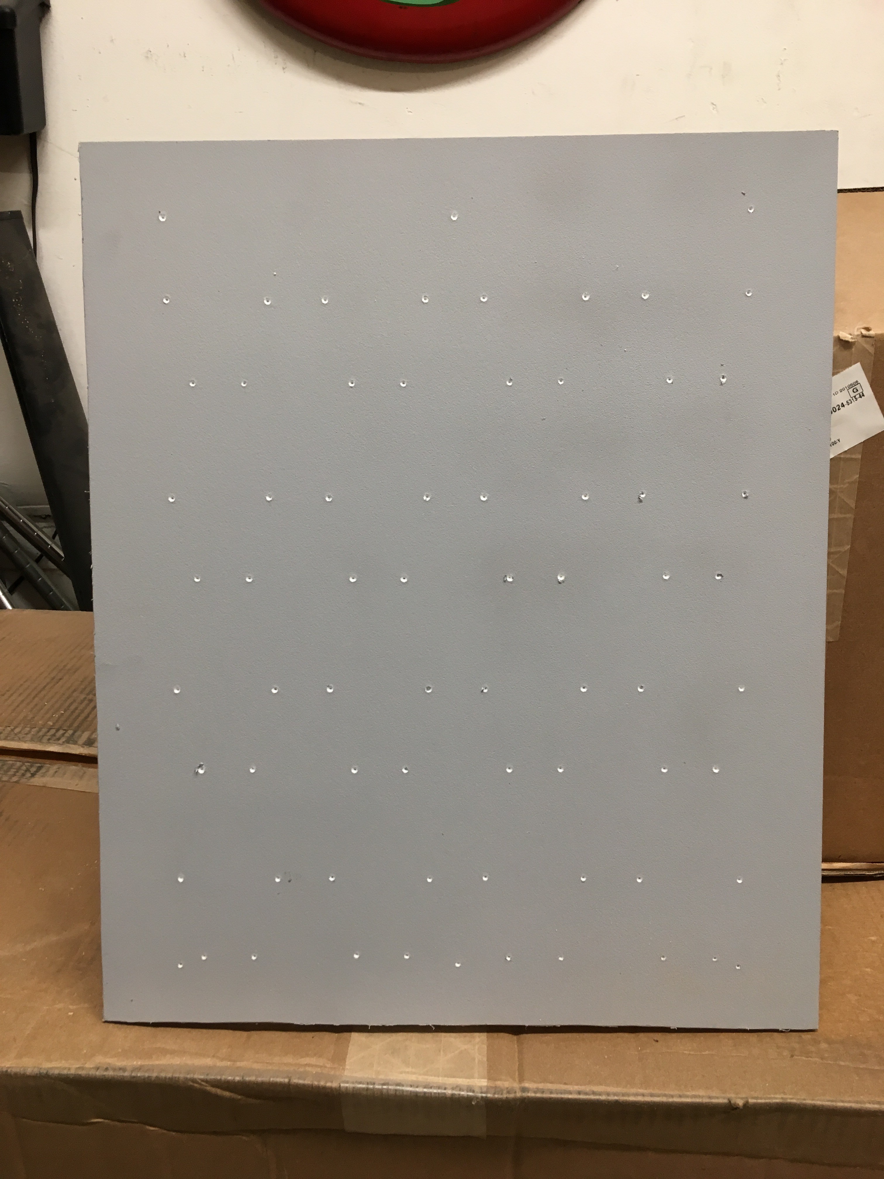
    then drill each hole on the drill press:

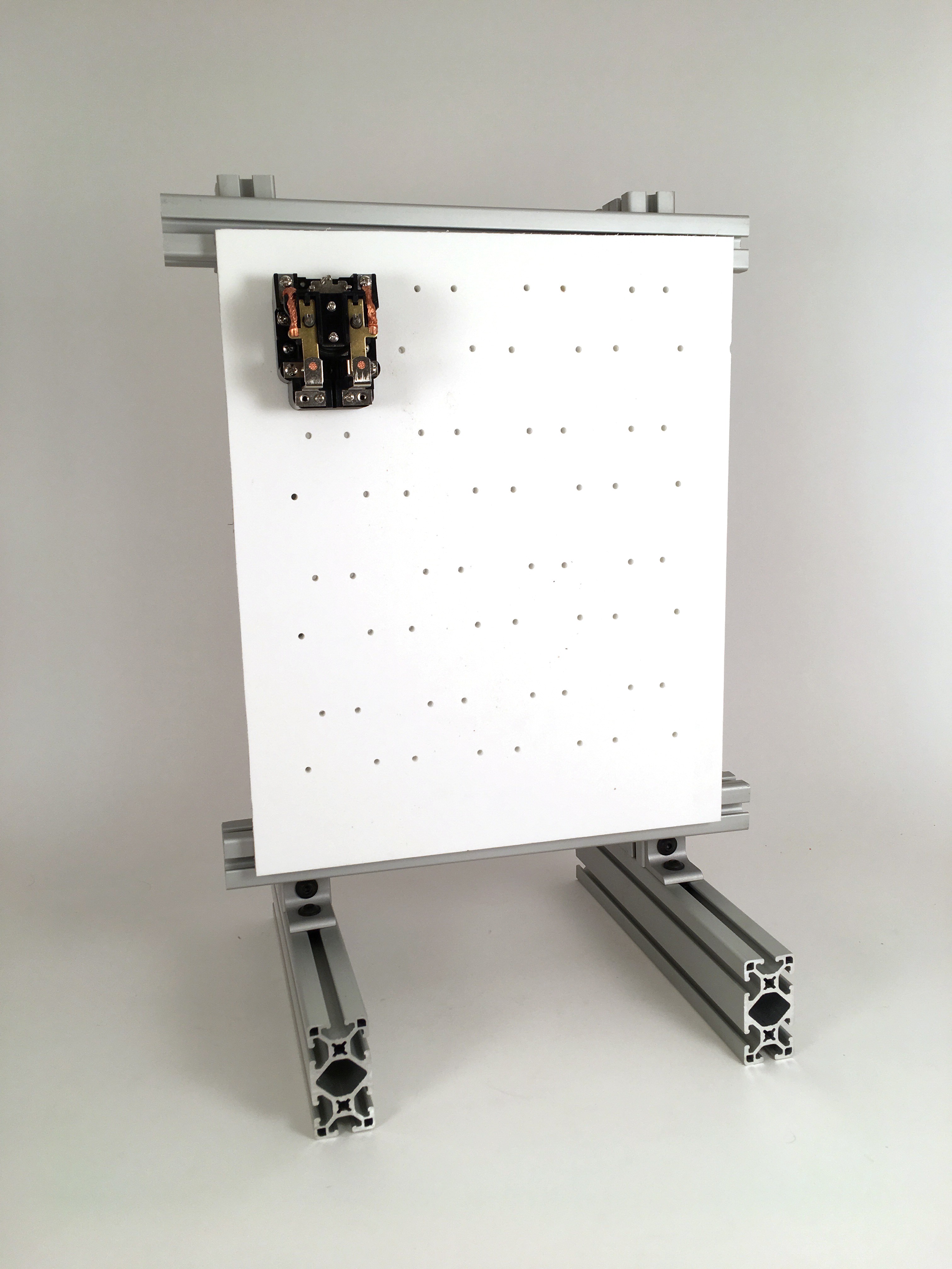
    Here's the first relay mounted:

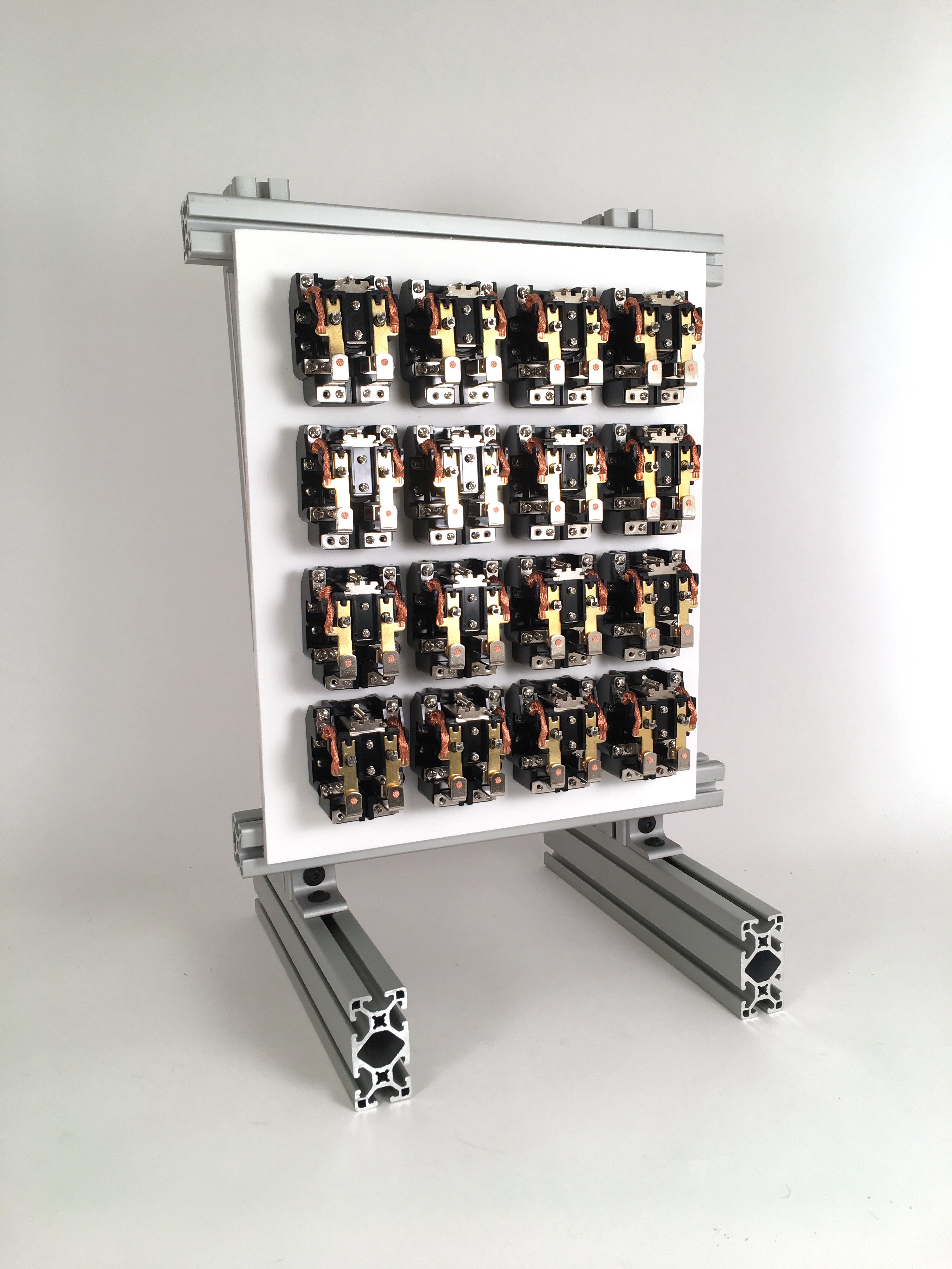
    And, the rest:

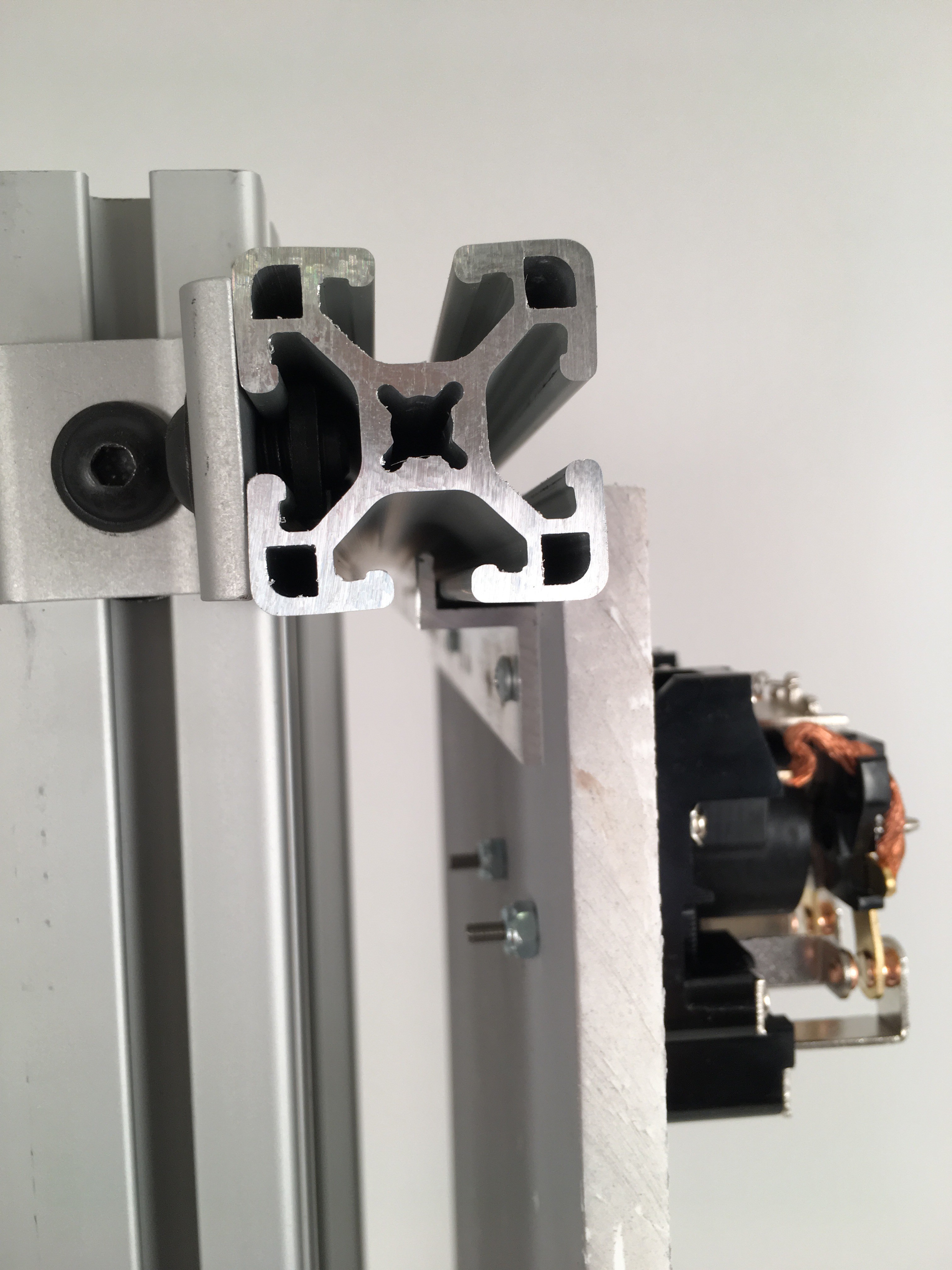
    The panel attaches via a Z strip at the top and bottom that engages with the horizontal extrusions:

    This mechanism allows the panels to be slid in and out quickly and easily while maintaining solid attachment and alignment.  There's about .04" of play front-to-back, so it remains to be seen if this will be a problem (e.g. causing a rattle when the relays are firing).

  • Proto frame

    Involute07/14/2018 at 04:21 0 comments

    I've assembled the frame for the prototype:

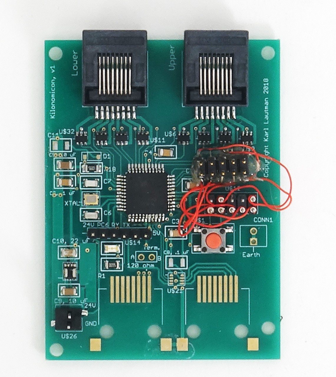
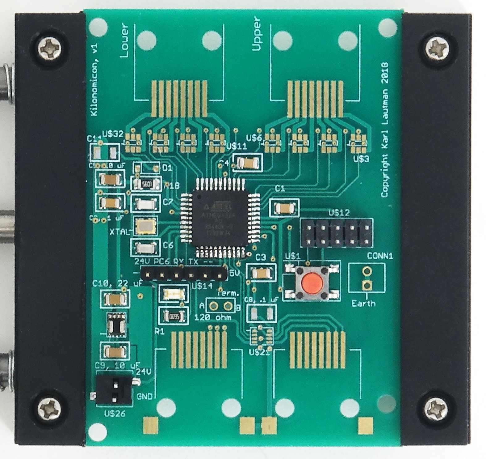
    I've also brought up enough of the controller board to drive the 16 relays with it:

    That mess of wires is to correct a footprint layout error I made when creating the 10-pin JTAG header in Eagle.  It's a relatively easy (if unsightly) fix, as you can see, so not worth respinning the board over just yet.  I'll wait until I decide on the replacement for the discontinued RS485 chip (that unpopulated 8-pin footprint between the two unpopulated RJ45 footprints) before doing that.

    The astute observer will notice the MCU is a bit askew, especially compared to the previous pic of this board.  That's because I borked it by accidentally shorting the two, leftmost pins of the test header immediately beneath it.  Unfortunately, those are the 24V and PC6 (bit 6 on IO port C) pins.  I removed the first chip with my hot air rework tool and installed the new one with a soldering iron.  I was a little careless with the install.  No shorts, though, and I was able to drive all the MOSFETs, as well as sense the pushbutton and drive the LED.  

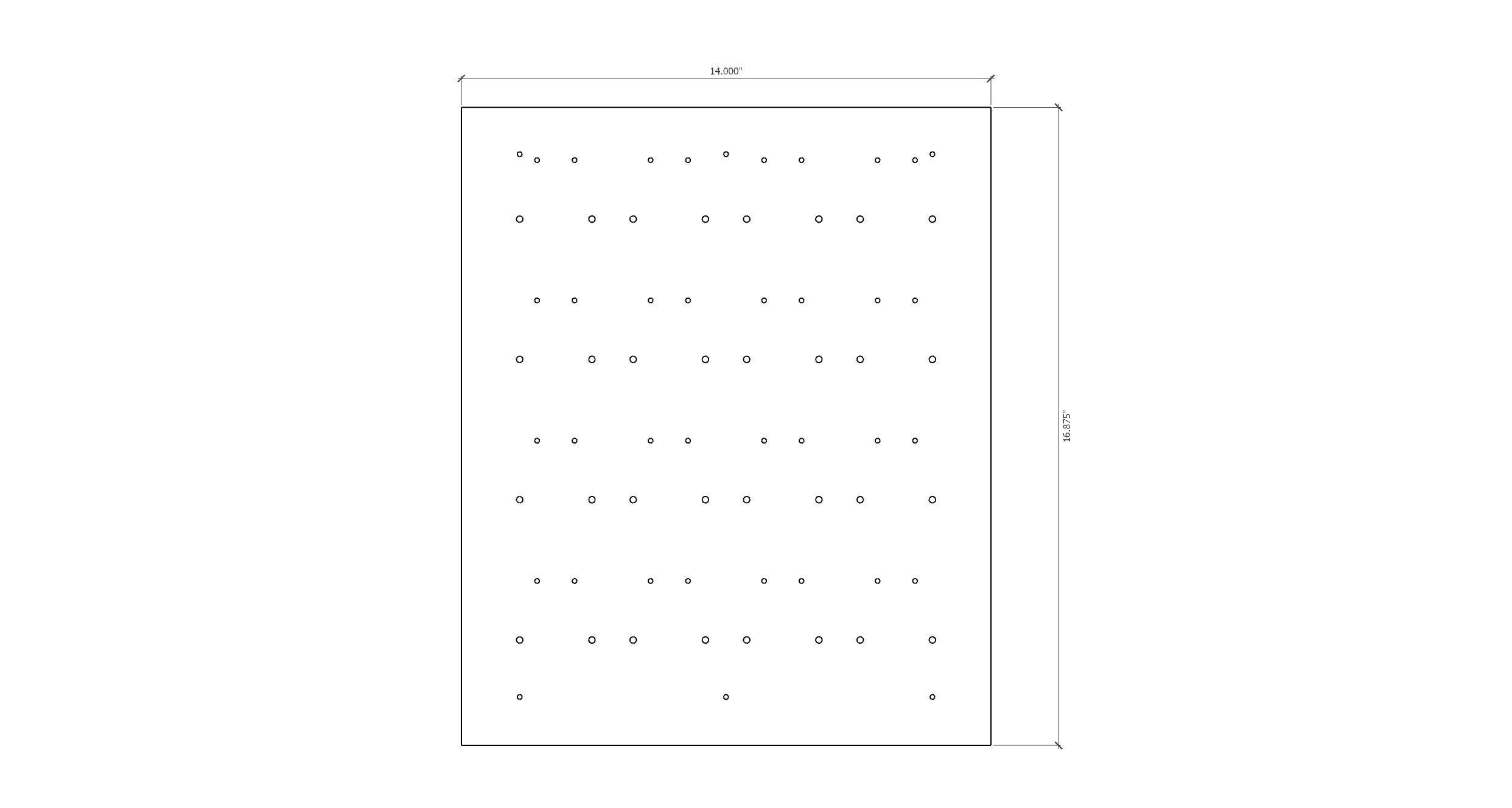
    The next step is to prepare the panel to receive the relays.  That involves drilling all these holes:

    This is just slightly too big for my milling machine.  I can send it out to be drilled for $40, or etch the holes in my laser cutter (which has an 18" x 24" bed), then use the etched depressions as guides for drilling on my drill press (the material is .5" HDPE, way too hard for my 40W laser to burn through).  I'm leaning towards the former, both for convenience and as a test of the driller.

  • Relays!

    Involute07/02/2018 at 23:34 0 comments

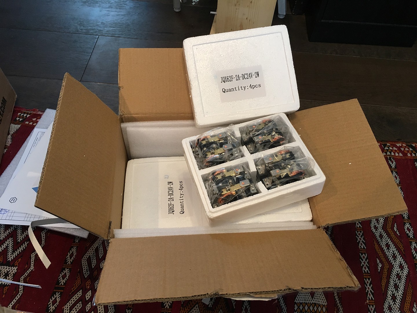
    16 relays just arrived from China for use in the prototype:

    I'll use these to make a single module:

    controlled by the controller board I'm slowly bringing up.  Here's the MCU and associated passives (haven't had a chance to power it up and load any firmware into it yet):

    With the prototype module I'll be able to test the controller board, relay sound, mechanical features, and even a two-node network (with another controller feeding commands to the module).  The 80/20 framing components should arrive Thursday.  Hopefully, I'll be able to validate the MCU by then and solder on the MOSFETS, RJ45 jacks, and RS485 controller (which Digikey just said Maxim is end-of-lifing; ugh).

  • Power supply works

    Involute06/30/2018 at 23:58 0 comments

    Kilonomicon will run primarily on 24VDC (lots and lots of 24VDC), but the controller boards will run on 5VDC (~20 mA typically, 250 mA worst case (if the RS485 bus shorts out)).  So, the plan is to convert the 24V to 5V at each board.  A linear regulator would be way too inefficient in this application, dissipating (24 - 5) x .02 = 380 mW.  

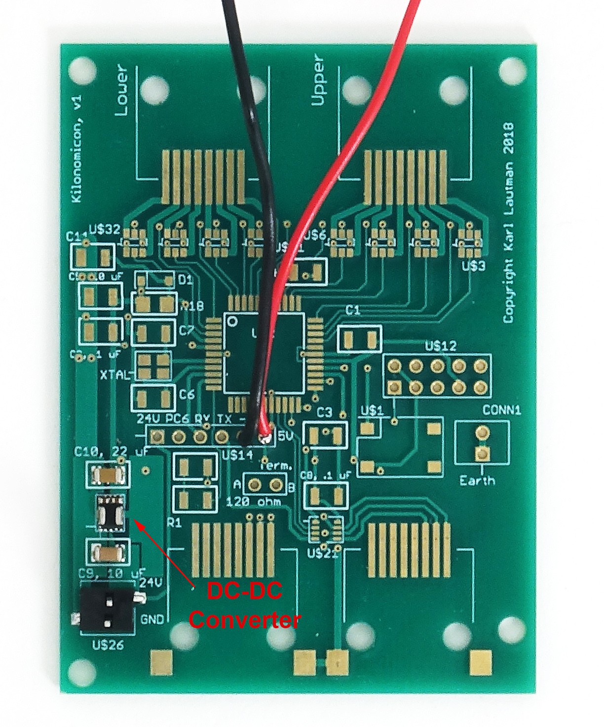
    Fortunately, there are lots of switch mode power supply (SMPS) solutions out there, some with efficiencies exceeding 90%, from roll-your-own out of discrete parts to drop-in modules.  One of the newest of the latter is the TI LMZM23600 (that's it by the arrow in the photo below).  There are several neat things about this converter, not least of which is its tiny size.  For scale, the test point holes above and to the right (starting with "24V") are .1" apart.  As small as it is, it's a PCB containing two caps, inductor, transistor switch, and intelligence.  It'll convert up to 42V to 5V at up to 500 mA (there are also 3.3V and adjustable output versions).  All that for the low, low price of just $4.14, quantity 1.  Just add input and output caps (which you can see above and below the converter) and you're ready to go.

    Unfortunately, like most SMPS solutions, it's least efficient at low power outputs.  In my case, that means most of the time it will be operating in the range of 40%.  It will still only be dissipating about 150 mW, less than half what the linear solution would, and won't even be warm to the touch.

    I used solder paste and a heat gun to solder it, the caps, and the power connector to the PCB and it works as advertised.  Next up, the MCU, its associated passives, and a pushbutton and LED.

  • PCBs!

    Involute06/27/2018 at 05:25 0 comments

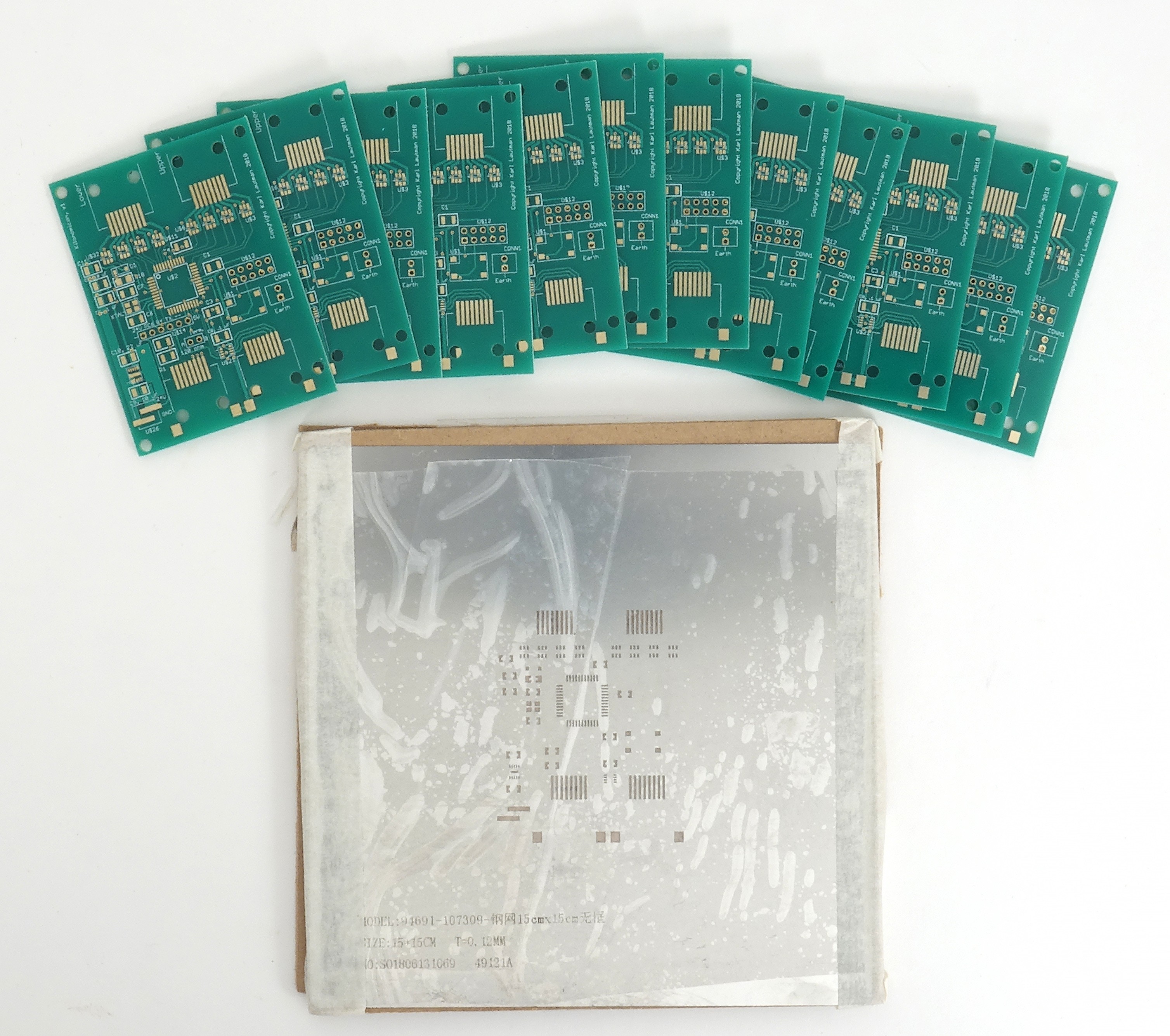
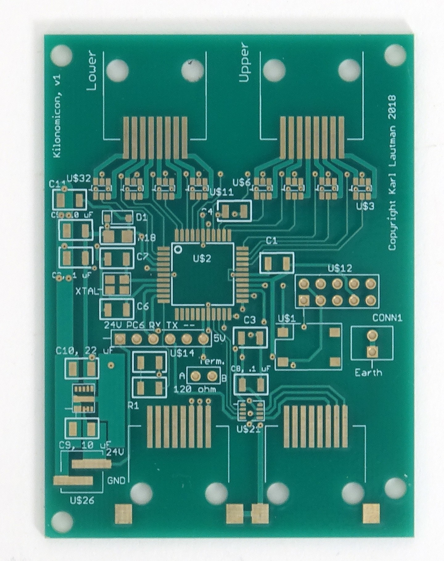
    I received my prototype PCBs (plus a stencil) for the module controller.

    I only needed two, but the minimum order from Elecrow is five.  On the other hand, the cost for 10 is the same as for five, so I ordered 10.  And they sent 12.  All for the price of $17, plus another $16 for the stencil, and $21 for DHL shipping.  Not bad (assuming they work).  

    I normally don't order stencils as they're easy to cut out of mylar on my laser cutter, but I was concerned about the DC-DC converter (the 10-pin part at the lower-left, between C9 and C10) as its fine pitch might be more than the mylar can handle.  Same for the eight MOSFETs across the top; $16 is cheap insurance.

    I'll start bringing up one of these boards in the next few days, though the 16 eval relays are delayed and won't get here until next week, probably.  Plus, I still need to design and order the prototype frame for the relays, which I probably won't do until I have them in my hand.  So, not a lot of clicking for, realistically, another month or so.

View all 6 project logs

Enjoy this project?

Share

Discussions

Mike Szczys wrote 06/14/2018 at 18:58 point

Music played by a 1000-piece mechanical relay orchestra? Sign me up!

  Are you sure? yes | no

Similar Projects

Does this project spark your interest?

Become a member to follow this project and never miss any updates