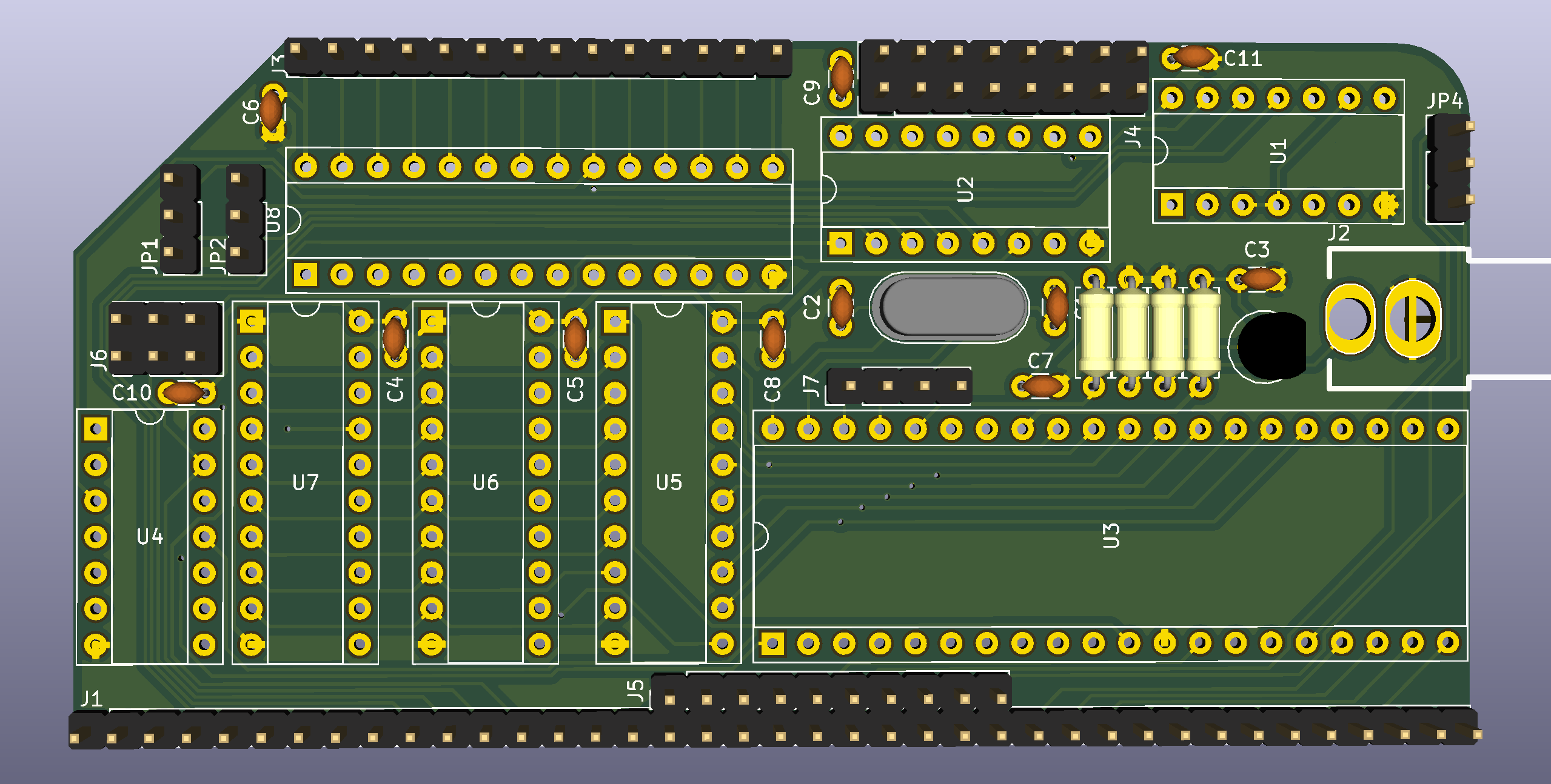
I've been working on a new revision of my board that will work with unmodified ColecoVision games. I had some success getting a few games to run by modifying the ColecoVision BIOS but many games bypass the BIOS and access the ports directly, so it would be a lot of work to modify them all for compatibility.

The new revision will have basically the same BOM as before with the addition of more jumpers. Based on feedback from Mark on the RC2014 mailing list, I have hopefully made it compatible with the Sord M5 computer as well.
Here's how the address decoding works:
- J4 configures address bits 7-5 which lets you select a block of 32 addresses: 00-1F (left) ... E0-FF (right). For ColecoVision, you would set this to A0-BF (6th position). For MSX, you'd set it to 80-9F (5th position). For Sord M5, you'd set it to 00-1F (1st position).
- J6 configures address bit 4. There are 3 options: ignore (left), 0 (middle), or 1 (right). This lets you use the entire 32 address range, the upper half, or the lower half, respsectively. For ColecoVision, you would set this to ignore (left). For MSX and Sord, you would set it to 1 (right).
- JP1 configures address bits 2 and 1. In the upper position, they must both be 0. In the lower position, they are ignored. For MSX, you would set this to the upper position. For ColecoVision and Sord, you would set it to the lower position.
- JP2 configures address bit 3. In the upper position, it must be 1. In the lower position, it is ignored. For MSX, you would set this to the upper position. For ColecoVision or Sord, you would set it to the lower position. This allows configuration of the correct ranges for all 3 systems:
- MSX 1 (98 and 99)
- ColecoVision (A0-BF, with BE and BF typically used)
- Sord M5 (10-1F; with 10 and 11 typically used)
For other Z80/TMS9918A systems, such as the SpectraVideo and MTX, it should at least be possible to configure a superset of the correct addresses, but it may not be possible to decode the addresses as precisely as the original system. Depending on what other peripherals such a system has mapped to any partially decoded addresses, this may or may not cause a conflict. This is the best that I can do without adding any more decoding chips, which I don't have room for on the board.
I also added a jumper (JP4) to output the TMS9918A's interrupt signal to either INT (upper position) or NMI (lower position) on the RC2014 bus. There is now a second row of bus pins to connect NMI to the RC2014 bus. ColecoVision connects the video interrupt to NMI, so this change was necessary for compatibility. MSX uses INT, and most other systems do as well.
Finally, I added a header (J7) with pins for (left to right) CPUCLK, GROMCLK, EXTVDP, and GND. This should allow the CPUCLK and GROMCLK signals to be used via jumper cables with other boards the need them, for example on the Sord M5. It should also be possible to daisy-chain multiple TMS9918A chips using the EXTVDP signal, or to genlock an external video source. I added a GND pin to use with an external video source if needed.
I am going to check these changes into Github now but I am waiting to design my SN76489A sound card and ColecoVision joystick interface boards before I have them manufactured.
 J.B. Langston
Discussions
Become a Hackaday.io Member
Create an account to leave a comment. Already have an account? Log In.