 igorfonseca83
-
1Tools and Materials
The following tools and materials were used in this project:
Tools and materials:
- 3D printer (link). It was used for printing the case where the electronics are encloused.
- Solder iron and wire. Some of the components (ESP8266 Firebeetle and LED matrix cover, for instance) doesn't come with soldered terminals. I needed to solder some wires or pins in order to connect those devices.
- Shrinking tube. l also had to solder the wires of each load cell. A piece of shrinking tube might be used for a better isolation of the conductors.
- Screwdriver. The structure is mounted using some screws. A set of screwdrivers was used.
- Screws. I used some screws to attach the 3D printed parts to the base of the scale.
- M2x6mm Bolts. They were used for mounting the electronics inside the case.
- 1.75mm PLA (link / link / link) of any color you want.
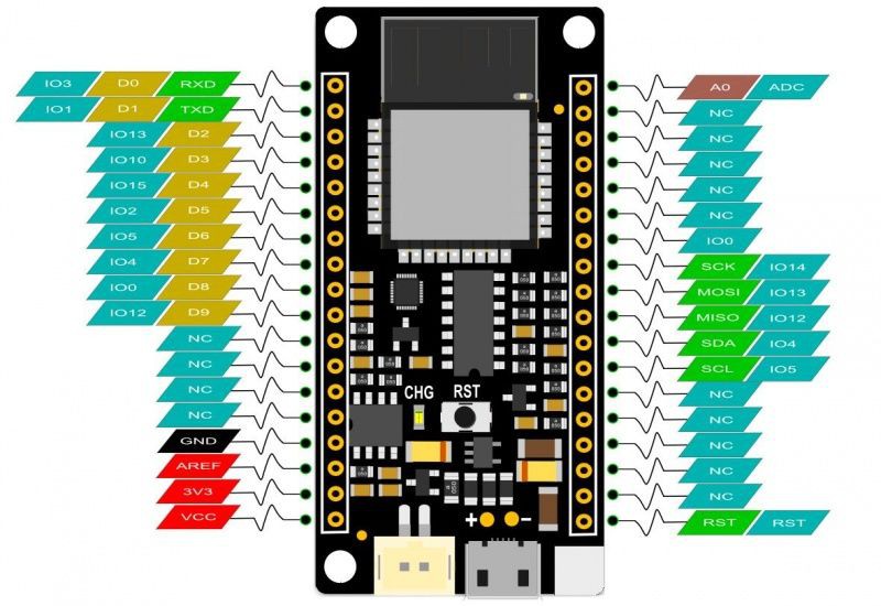
- FireBeetle ESP8266 dev board. It's really easy to use and program using Arduino IDE. It has built-in Wi-Fi module, so you can use it in a variaty of projects. It has a connector for a 3.7V battery, which was really usefull for assembling this project. I has also a built-in battery charger. It will recharge the battery when connected to an USB plug. You can also use other ESP8266 based bords (link / link / link) if you wish. Deppending on the board you choose, it would be a little more difficult to connect and recharge the battery, or to connect the LED matrix. The dimensions of the case will also need to be verified.
- Firebeetle covers - 24x8 LED matrix. This module easilly fits on top of the Firebeetle ESP8266 dev board. I used it to display the values measured by microcontroller, display some status, etc. You can also use other kinds of display if you wish, like ordinary LCD displays (link / link) or OLED displays (link / link).
- HX711 module (link / link / link). This works as a load cell amplifier. Four strain gauge load cells are connected to this module, and it communicates on a serial communication with the ESP8266 microcontroller.
- 50kg load cell (x4); (link / link). They are used to measure the weight of the user. Four of them were used for a maximum weight of 200kg.
- Micro USB cable;
- 6 female-female jumper wires;
- 2 x 15 mm plywood sheet (30 x 30 cm). It was used for the base of the scale.
The links described above are only a suggestion of where you can find the items used in this tutorial (and support my future hacks). Feel free to search for them elsewhere and buy at your favourite store.
I used a FireBeetle ESP8266 dev board, which was kindly supplied by DFRobot. It worked perfectly! I also tested the code with a NodeMCU board. It also worked fine (although the time for connection was significately longer... I still don't know why...).
Did you know you can buy a Anet A8 3D printer for only $168.99? Get yours! http://bit.ly/2x04H5B
-
23D Modeling
The smart scale was desgined using Fusion 360 CAD software. The model is composed of three different 3D printed parts: cover, case and foot. The case provides an enclosure for the electronics, protecting them from physical contact. Electronics are attached in the cover part (using some bolts). This part has a front visor, where the display is fitted. Load cells fit into the foot part, which allows the sensors to be attached to the base.
-
33D Printing
You can download all the stl files on the following websites:
https://www.thingiverse.com/thing:2934791
https://pinshape.com/items/45555-3d-printed-diy-wi-fi-smart-scale
https://www.youmagine.com/designs/diy-wi-fi-smart-scale
https://cults3d.com/en/3d-model/gadget/diy-wi-fi-smart-scale
https://www.myminifactory.com/object/3d-print-diy-wi-fi-smart-scale-66654
I printed the whole structure in PLA, usign two different colors. The whole print took me around 5h30, using 0.2 mm resolution and 10% infill. No supports needed.
This is a experimental prototype. Notice that it was designed for a given ESP8266 dev board model (the ESP8266 Firebeetle).
If you don't have a 3D printer, here are some things you can do:
- Ask a friend to print it for you;
- Find a hacker/maker space nearby. The parts used in this model can be printed quickly. Some hacker/maker spaces will only charge your for the materials used;
- Buy your own 3D printer. You can find the Creality3D CR10 for only $359.99! Get yours at http://bit.ly/2JIUVrf
- Improvise! You can try to assemble a structure without 3D printed parts.
-
4Woodworking
The base of my scale was mede of two 15mm 30 x 30 cm sheets of plywood.
I made some whole using a screwdriver for passing the wires of the load cells, and for attaching the 3D printed parts.
-
5ESP32 Firebeetle and LED Matrix
Some of the components had to be soldered before their installation on the case.
I soldereded a male-female pin bar to the ESP8266 module. This way I could connect the LED matrix shield on its top, on the female connectores, and use the male pins for the connection to the HX-711 module (for the sensors).
I also had to solder a male pin bar on the LED matrix, so that it could be connected to the ESP8266 module.
-
6Preparing the Electronics: HX711 and Load Cell
Solder HX711 terminals
Most HX711 boards come without soldered pins on their terminals. I soldered a male pins bar, which was used later for the connection to the ESP8266 development board and forthe load cells.
Solder load cells signal terminals
Load cells usualy have three wires (black, white and red). The red wire is the signal one, which I connected to the HX711 module. For that I used two female-female jumpers. I cut one side of the jumper and solder it's wires to the load cell red wire. I used a shrinking tube around the solder for a better isolation.
I also had to solder white and black load cells wires, but it was done only after the sensors were positioned and attached to the structure.
-
7Assembling the Scale - Pt1
First I had to fit the sensor inside the 3D printed foot parts. They were locked inside this fame, and later attached to the structure using some screws.
I used four M2x1.6mm for attaching the display to the 3D printed cover part. Two more bolts were used for the HX-711 module. The ESP8266 is connected to the display module using a female pin bar. A four-wire jumper connects the HX-711 to the ESP8266 module. More on this on later steps.
The cover part fits inside the 3D printed case. The case has two other rectangular holes: one for the cables between the HX-711 module and the load sensors, and other for the USB cable used for powering up the circuit and uploading the code. The case was closed only after the connection of the sensors (shown in next step).
-
8Assembling the Scale - Pt2
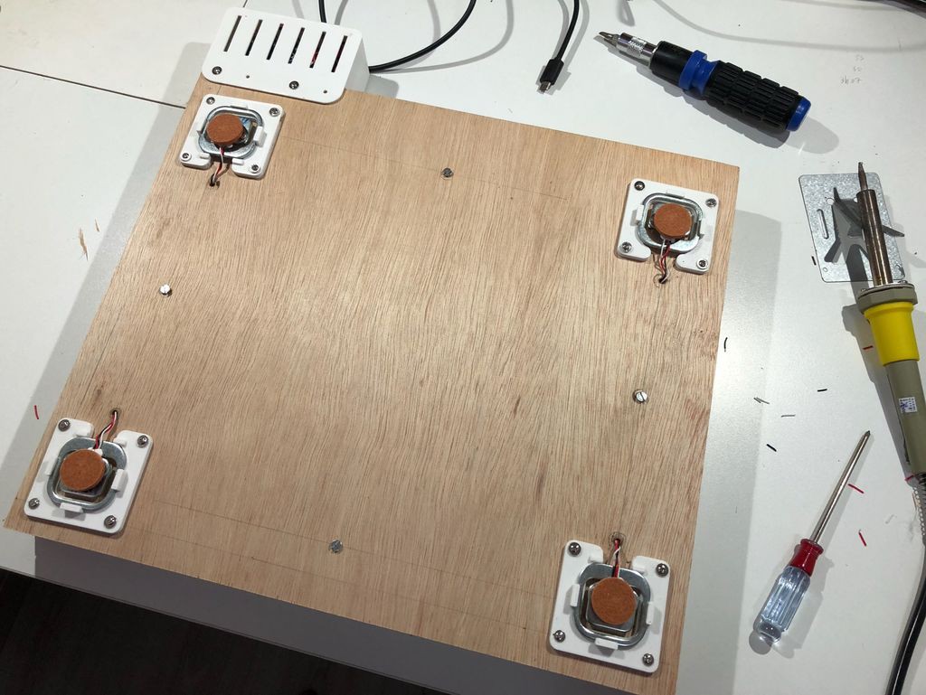
Once 3D printed parts and wood panels were ready, it was time to assemble the structure. The following steps were taken:
1. Installed the load cells on the first wooden pannel. I used for screws for each.
2. A hole was made on the wooden panel right above each sensor. The cables passed through those holes to the other side of the pannel.
3. Soldered the wires according to the image shown in next step.
- Upper left white wire <=> Upper right white wire
- Lower left white wire <=> Lower right white wire
- Upper left black wire <=> Lower left black wire
- Upper right black wire <=> Lower right black wire
Use some shrinking tube to isolate the wires.
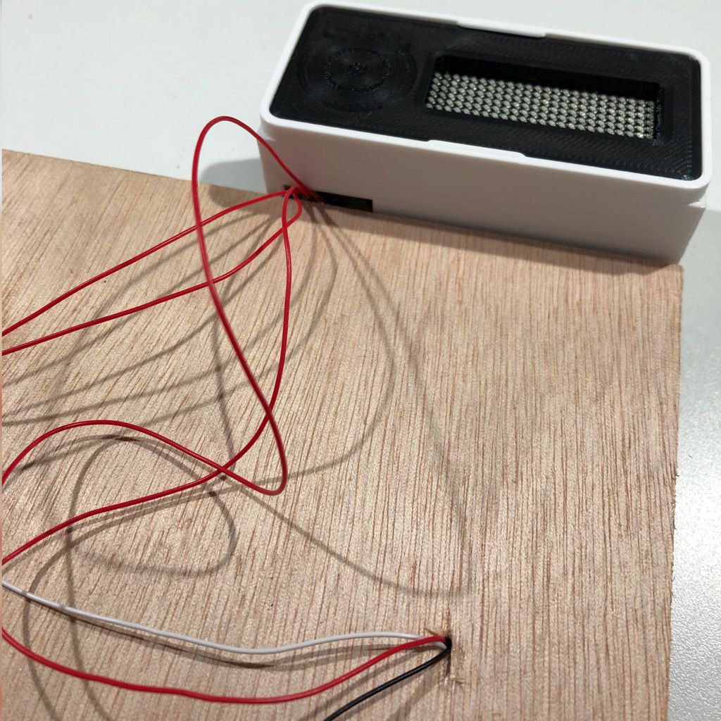
4. Attached the 3D printed case. Passed the red wires through one of its holes and connected them to the HX711 module.
5. Installed the second pannel on the top of the first one, using four screws.
![]()
![]()
![]()
-
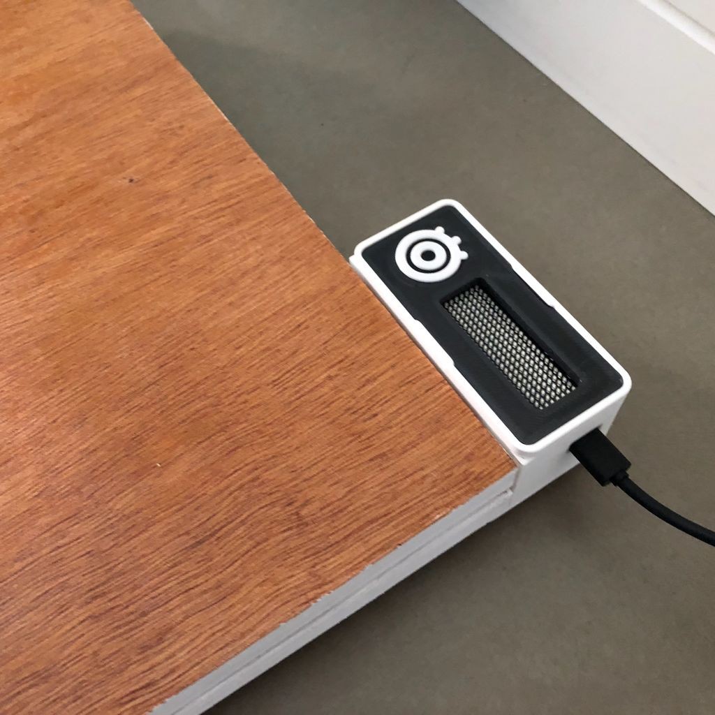
9Final Touches
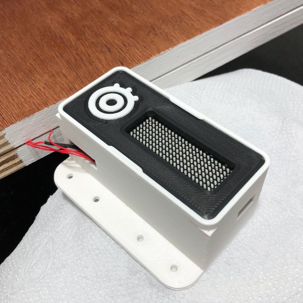
I painted the wooden panels and add some details to the case, for a better finishing.
You might choose different colors or even add a different material to the surface.
![]()
![]()
-
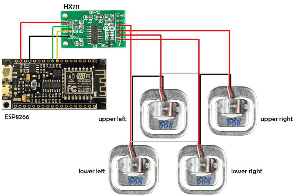
10Wire Up the Circuit
Each device was connected according to the schematics.
HX711 - input:
- Upper left load cell signal (red wire) => HX711 E- pin
- Lower left load cell signal (red wire) => HX711 A+ pin
- Upper right load cell signal (red wire) => HX711 A- pin
- Lower right load cell signal (red wire) => HX711 E+ pin
HX711- output (use a female-female jumper wire):
- HX711 Vcc pin => ESP8266 3.3V pin
- HX711 GND pin => ESP8266 GND pin
- HX711 SCK pin => ESP8266 GPIO 12 (pin D9)
- HX711 DT pin => ESP8266 GPIO 0 (pin D8)
Display module:
- Connect it on the top of the Firebeetle ESP8266
When everything is wired up, close the case, plug a USB cabe on the ESP8266 and get ready for uploading the code.
![]()
![]()
DIY Wi-Fi Smart Scale (with ESP8266)
A smart bathroom scale, using 3D printing, ESP8266, Arduino IDE, Adafruit.IO and IFTTT app.
Discussions
Become a Hackaday.io Member
Create an account to leave a comment. Already have an account? Log In.