 Jasper Sikken
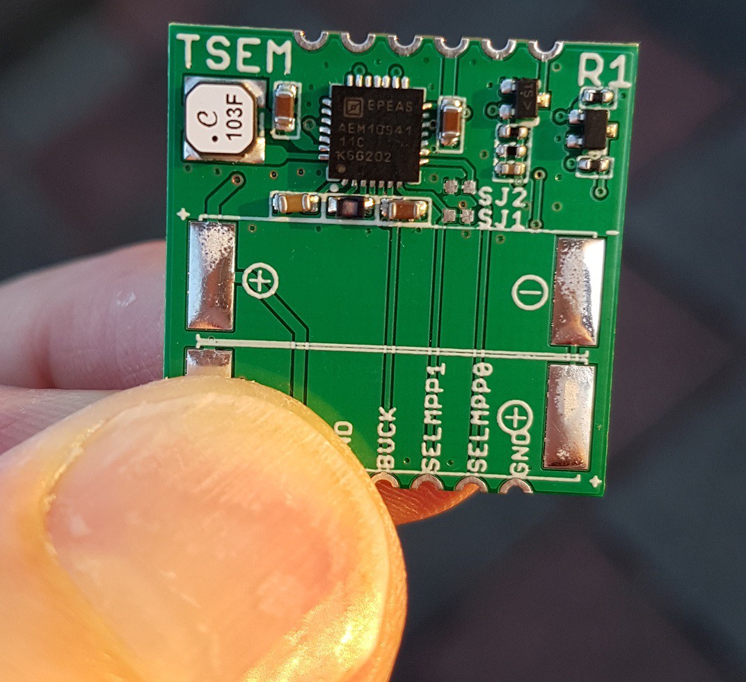
Today I have received the components from Farnell and the AEM10941 harvesting ICs from E-peas. I used a solder stencil from Elecrow, chipquik SMD291SNL10 solder paste and used an solder paste spreader from OSH Stencil, basically a credit card sized piece of plastic. I placed components on 3 PCBs.
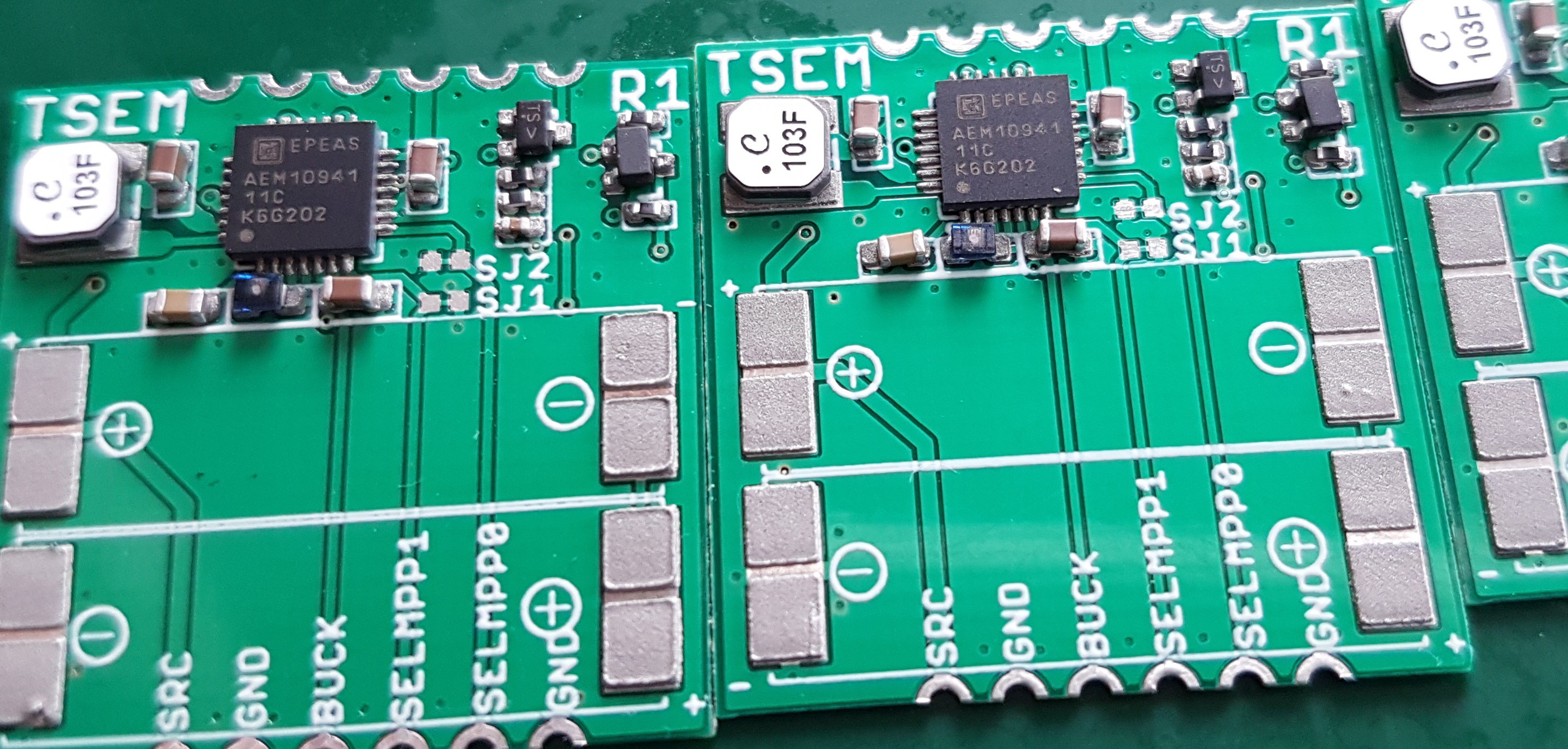
Using a Yihua 858D hot air gun I have reflowed the board without the solar cells, those I soldered manually because I didn't want to heat them for too long. According to the datasheet they should be soldered using low temperature solder paste or manually but very shortly.
Then it was time for the first test. I soldered a small Lipo battery (20x20x6mm) and I went outside, the sun had just set I could measure the 3.3V output which is only available after cold start.
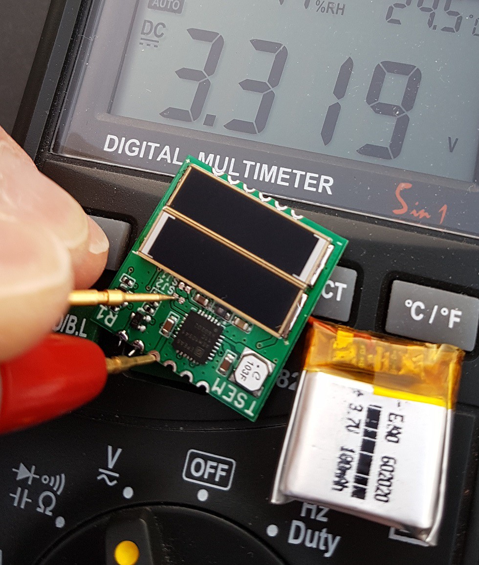
In addition I measured the boost voltage 4.0V and the buck voltage 2.2V and this all is as expected. I measured 0.95V on the solar cells output which is as expected (about 2 x 0.5V). Aparently it is working, but I need to do some more testing to confirm. For example comparing the solar current to the battery charge current, which should be about 5 times lower. After that I can power an application with it. I have a $15 bluetooth low energy temperature/humidity sensor that advertizes sensor data at some interval.
Discussions
Become a Hackaday.io Member
Create an account to leave a comment. Already have an account? Log In.