 Johannes
Well, after I had some drawbacks with the scanner-board, I focused on another part of the project: the sender-board.
This device will provide an ultrasonic pulse (or burst).
I learned some things while etching the first board, which led to great improvements for the second board.
So here we go, the board is ready for assembly:
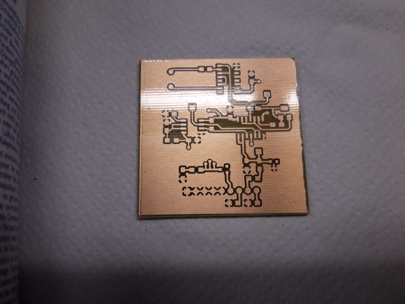
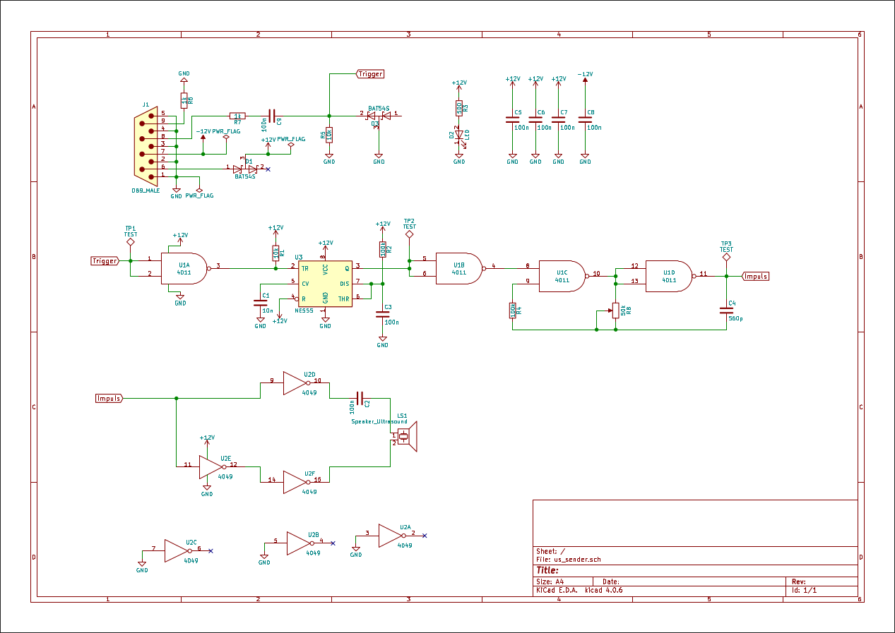
This time I first built some parts of the circuit on protoboard to test my concept and changed one or two things. So the current schematic looks like this:
Update: Finished prototype of sender-board
Yesterday I finished the sender board.
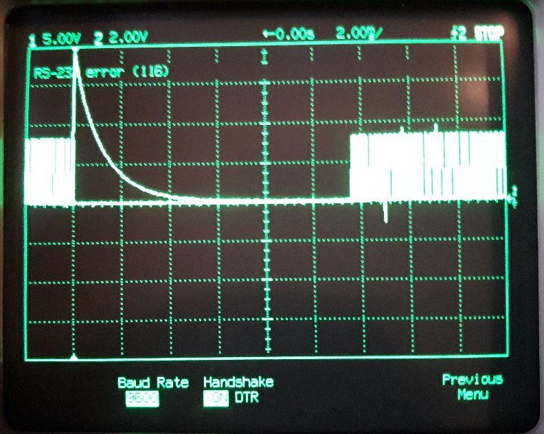
I had to fix two things as I had the polarity of the NE555's output wrong (pulses were sent when no trigger was present, see photo below) and the TRIGGER line was missing a pull-down resistor.
After that, here is the result:
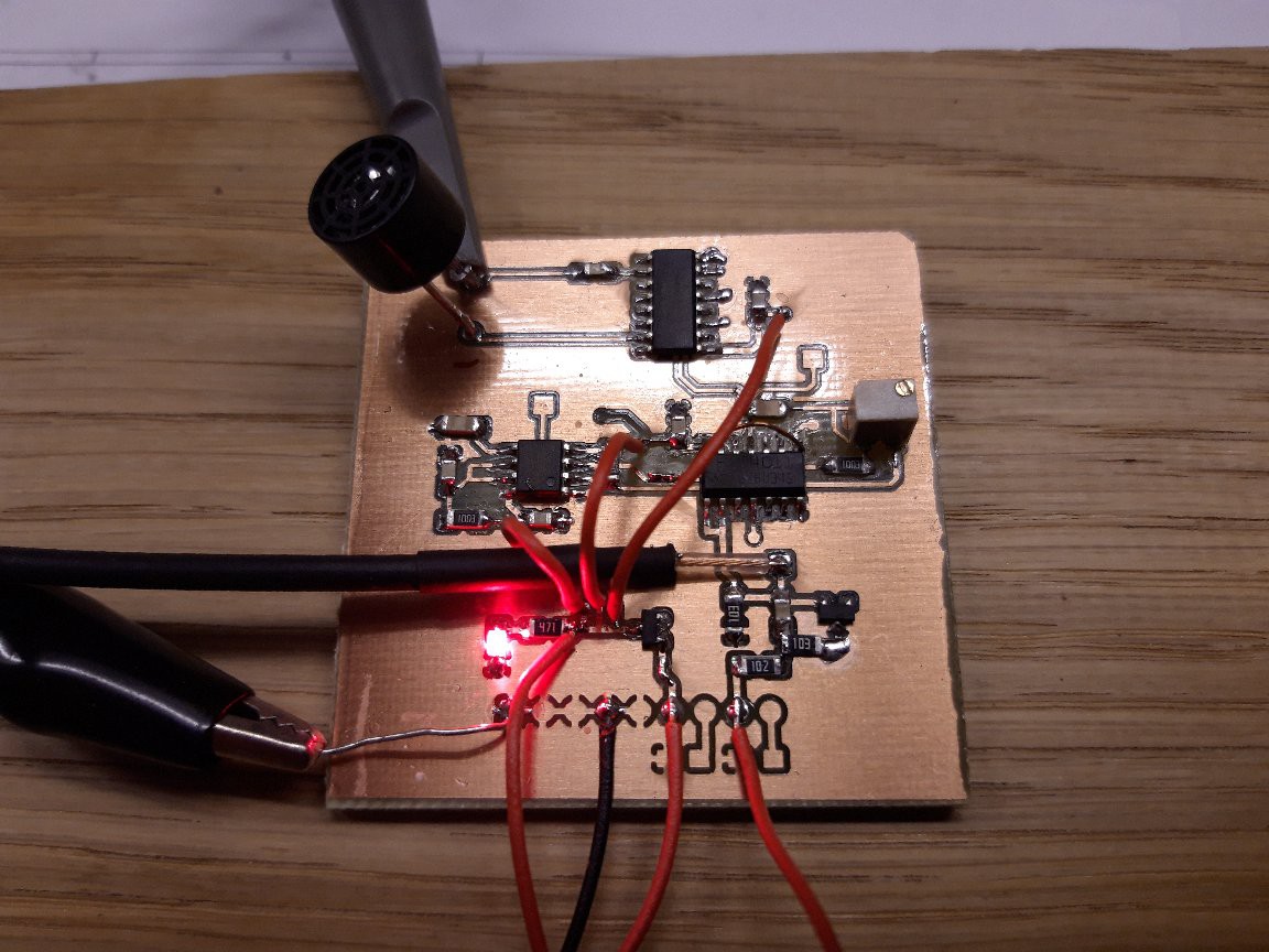
There is a BNC wire which is used to trigger the scope
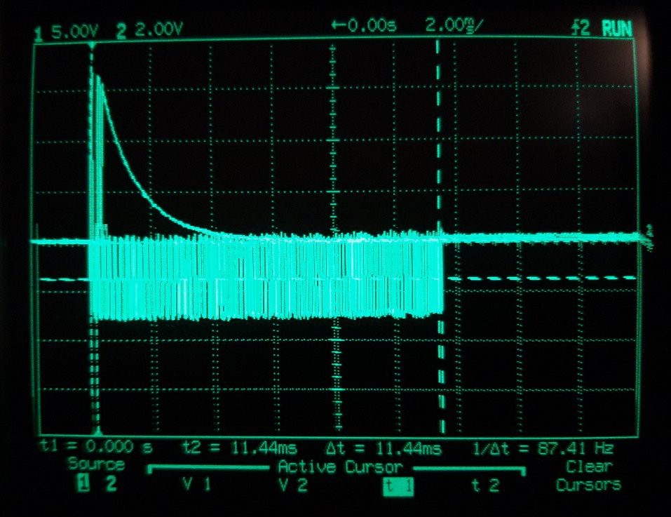
The burst is now 11.44ms long. Maybe this has to be adjusted later.
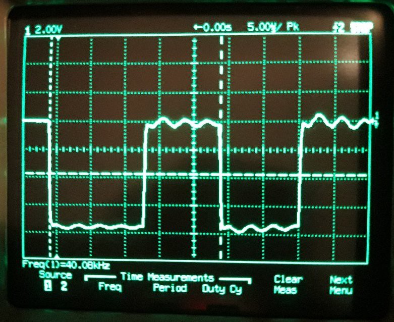
The oszcillator is set to 40.08 kHz but will surely drift in time.
Discussions
Become a Hackaday.io Member
Create an account to leave a comment. Already have an account? Log In.