I had some time since my last log and a lot of thoughts about the current setup.
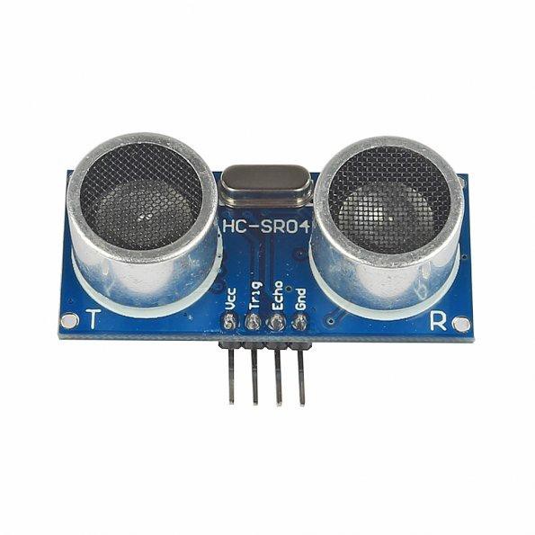
One thing I thought about is lobes of the sensors. There is a HC-SR04 datasheet here, where this image can be found:
I guess, I will need a much broader directivity, at least for the sender.
Second thought: signal strenght.
Maybe a more powerful sender can enhance signal strenght on the receiver part.
This leads to the topic, I'll cover next: different sensor types.
I found some random sensors on e*ay.
First, I'll take measurements about their directivity and power then I'll make changes to my test rig.
After all I do want to believe that this project will succeed.
HC-SR04
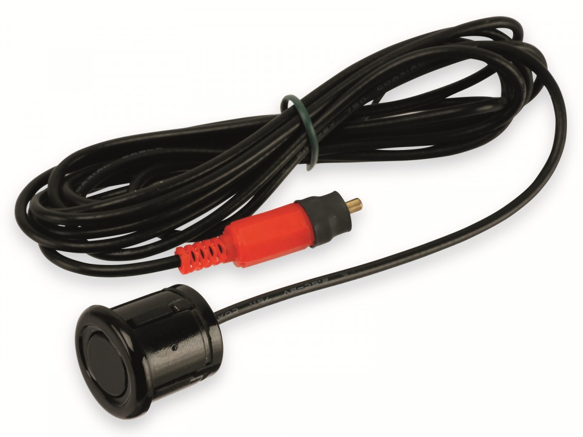
K-14WP10
Something I call "the cone"; with potetially very broad directivity. I have no idea, what this thing was used for, I could not find any datasheet.
#### Edit1:
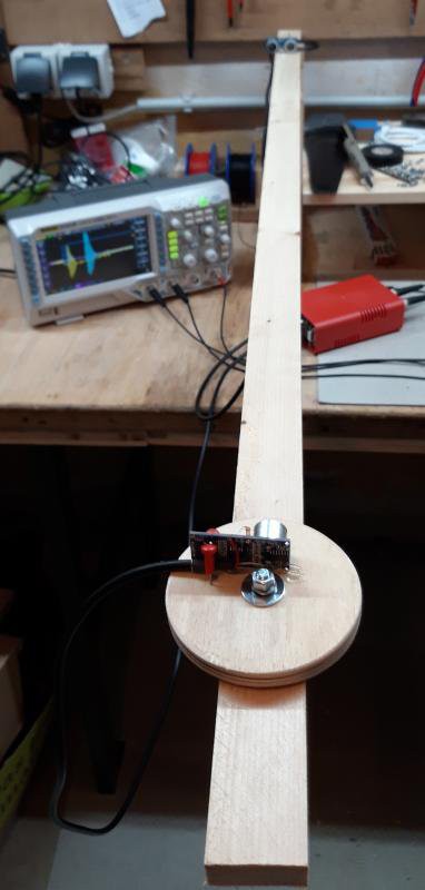
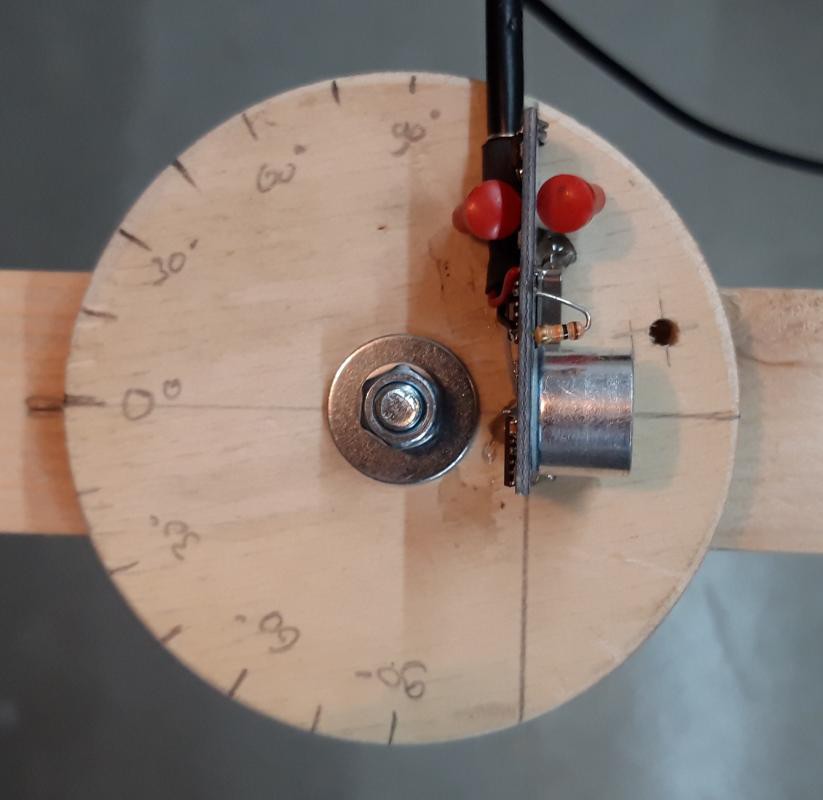
To measure directivity I created a small test-rig.
There is a sender-element at the end of the rail, connected to my red box. The rail has a wheel attached that can be rotated. I guessed that eccentric mount does not affect the measurement a lot, so I mounted the sensors a little bit of centre, because it was easier this way.
Likewise with "the cone". Here my HC-SR04 Sensor mounted inside the plastic case.
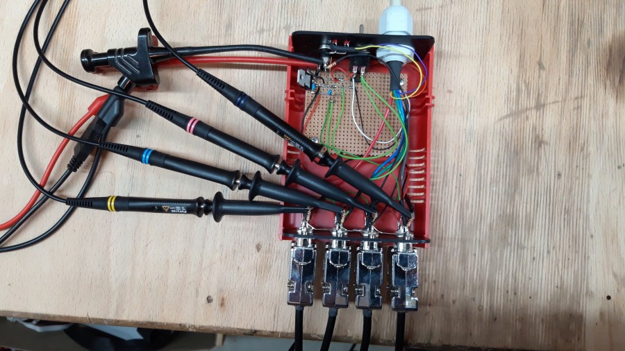
I did modify the red box a little bit, so it can be connected to my scope.
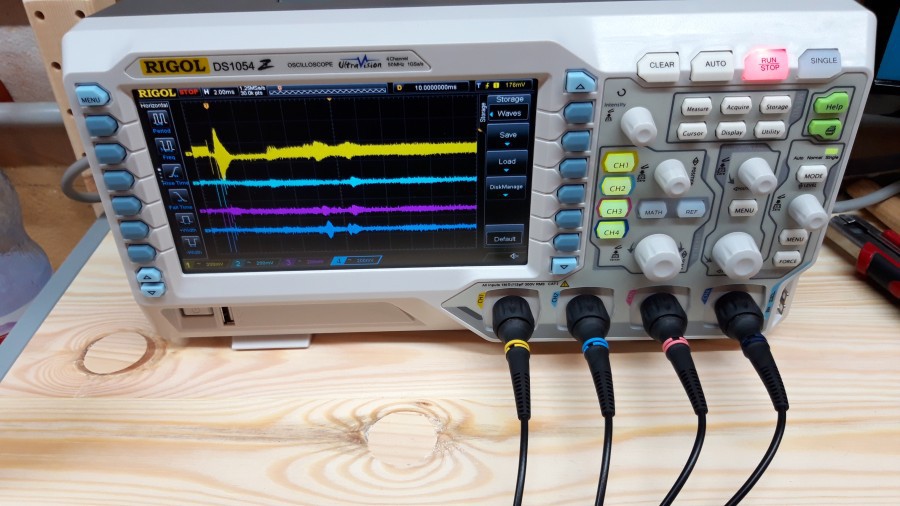
So after all was set up, I took measurements of signal strength over several angles.
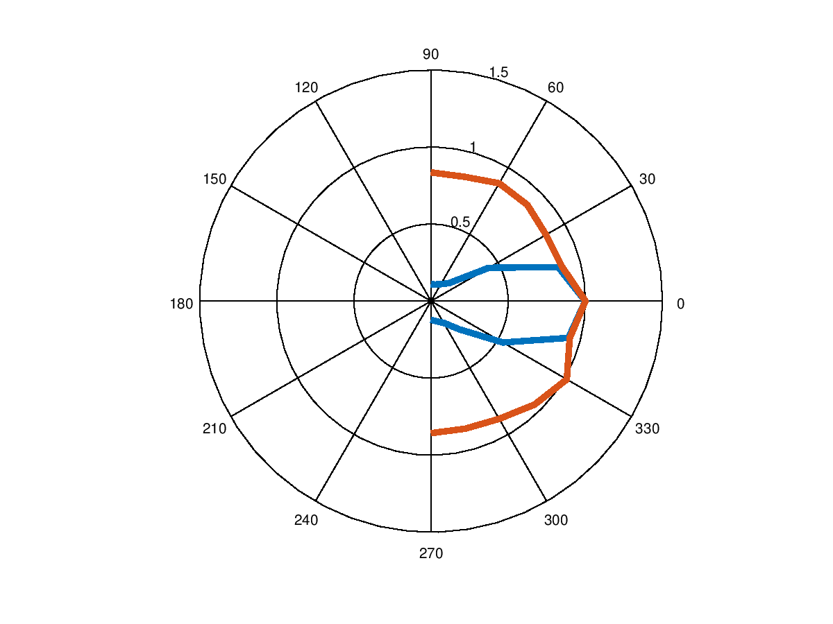
Blue is directivity of HC-SR04 and red of 'the cone'.
I'm very happy that I somewhat could reproduce the diagram from the HC-SR04 datasheet.
Earlier I did mention another sensor K-14WP10, this sensor will need a preamp which I didn't want to build right now. Therefore I just compared the two.
Just as said before, broad directivity is important for me, so next time I'll use 'the cone' for taking measurements.
####
Edit2:
In the diagram above each sensor directivity is normalized against its amplitude at zero degrees.
For 'the cone' aplitude at 0° is lower than the amplitude of HC-SR04.
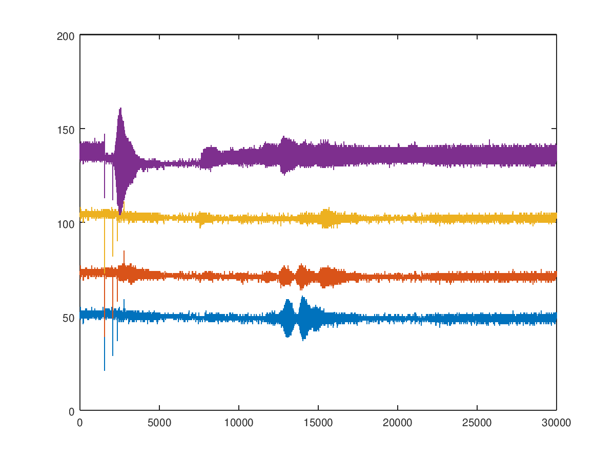
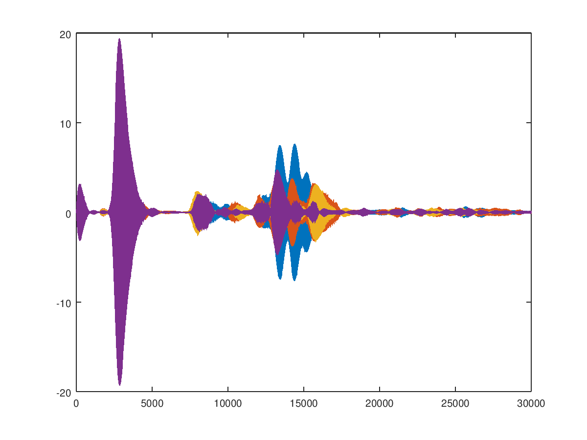
Then the raw data was analysed with octave. Therefore I wrote a script that reads the file my oscilloscope writes to an USB flash drive.
raw signals
filtered signals
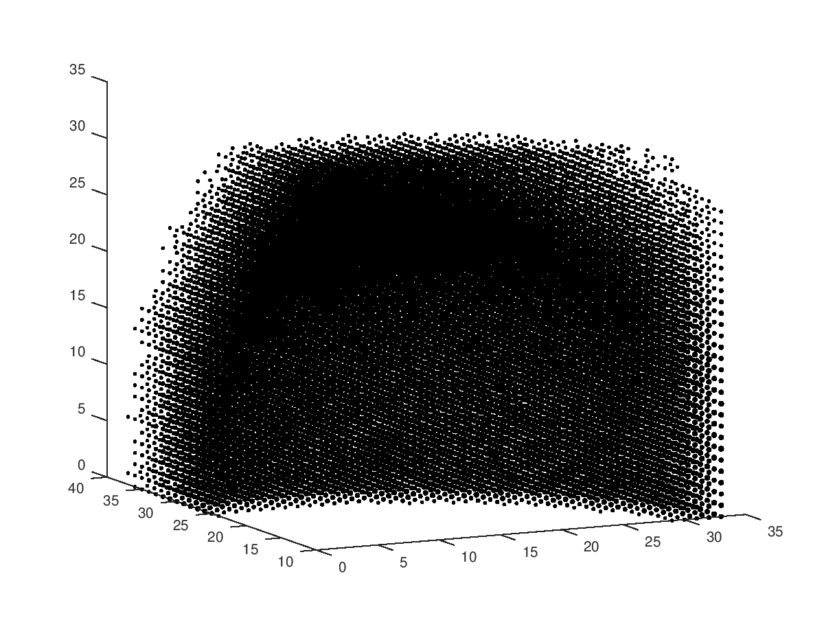
Finally the filtered data should create an 3D image. Which - so far - does reproduce something that looks nothing like the first image. Bummer.
What I rate as success is that the filtered data looks like I anticipated. Maybe I made a mistake with calculating the 3D volume, anyway I'll keep hacking until this works.
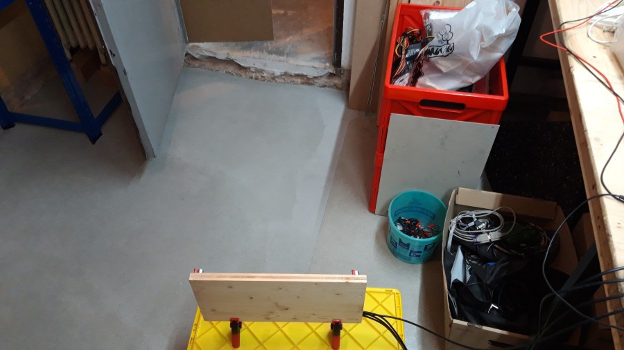
Last month there had been three major drawbacks on this project. Firstly some pipe in my workshop broke, so this had to be taken care for. Secondly water from this pipe killed my computer I used to use in theworkshop and thirdly also my oscilloscope is damaged.
Therefor I will continue to write updates, once I've taken care of these spokes in my wheel.
Some time ago I was lucky to obtain several measurement daq PCI cards. With my card, I'm able to acquire data from 8 channels simultaneously at 200kHz sample rate. Those sold at several hundred € which is quite cheap. If you're curious about the the card, this is the company's homepage with more details. One reason I chose this model is that it's supported by the open source driver comedi and I'm using Linux on my computer.
I've been working with devices like these cards for a long time, but not for my personal projects, especially high-end cards sell for several k€s which is all right when working on a project for a big company but not if it's your personal budget.
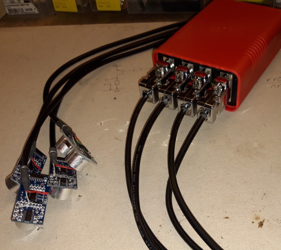
In my last project log I mentioned the red box. It will act as an adapter between my sensors and my daq card.
For safety reasons I added ESD protection inside the red box. This is just an 1kΩ resistor followed by two diodes per channel.
To trigger the ultrasonic burst a push button is connected to the HC-SR04s trigger lines.
Finally an external power supply delivers 5V to all four boards.
Right now as I'm writing this, I did not take any photos, but will add them later.
Now the next step is writing software to read out data from my daq card and analyse the waveforms.
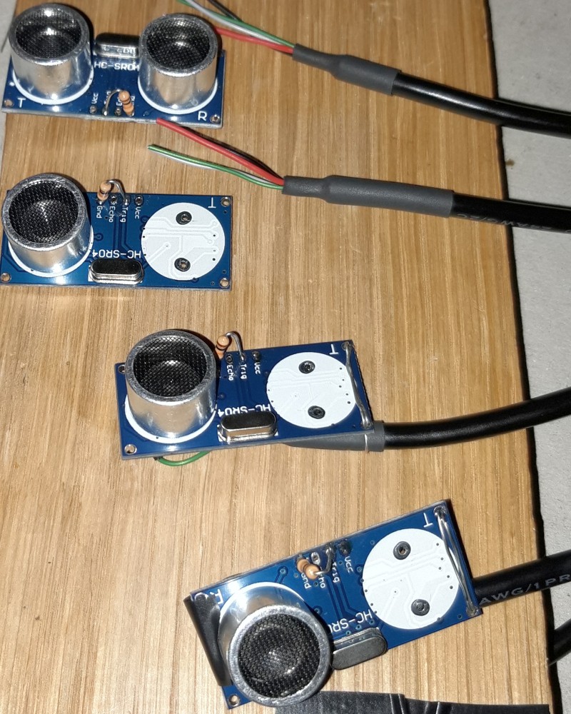
Some days ago I got tired of messing around with my circuits and finally ordered some HC-SR04 boards. There is everything I need packed together on one board: Transmitter and receiver and some controller.
Here I found a really good analysis of the HC-SR04. It seems like its receiver circuit is quite simillar to mine, allthough it works ways better.
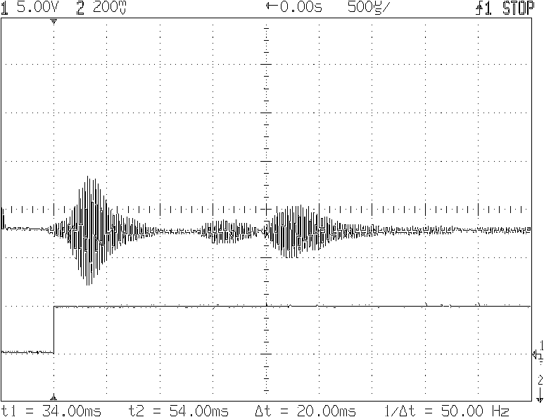
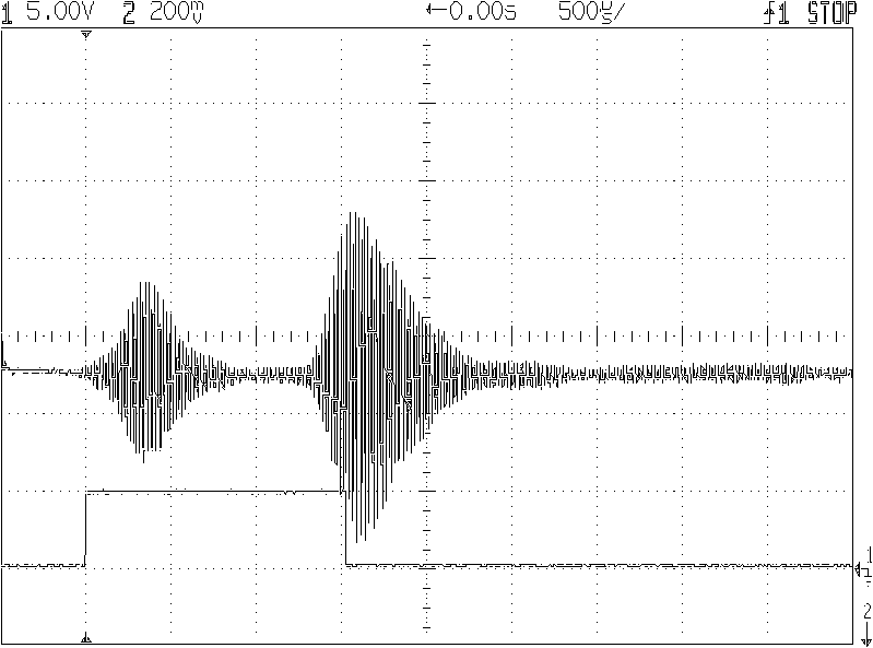
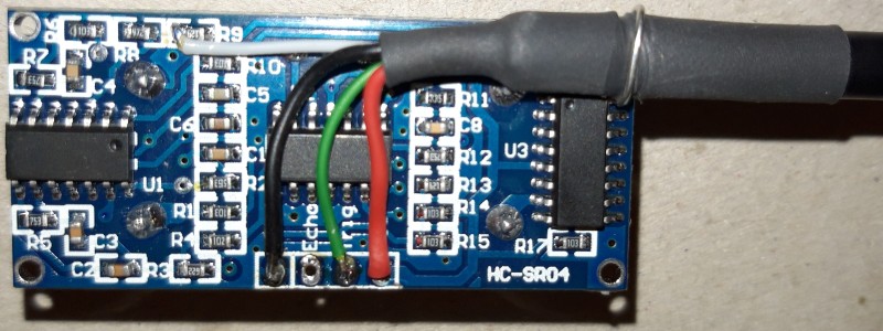
With this plan on hand, it took me only a few minutes to capture the next two images.
What can be seen is the input of the receiver after the third input stage (analogue, I want to capture this) and the related output of the controller (TTL, won't be useful for me).
With different distances to an object moves the time between sended and received pulse, on the first measurement the distance was ~35cm, the second time it was shorter.
Update:
Here is a photo of one transmitter/receiver (top) and three receivers:
Note that I removed the transmitter and added a pull-down on Trigger-In line. For connecting the boards I used USB cable, it's got a shield and hopefully running power and signal lines together is no big deal for this application. If signals are bad, I'll swap the cable or add a second, shielded cable for the analogue signal.
Update 2: more photos!
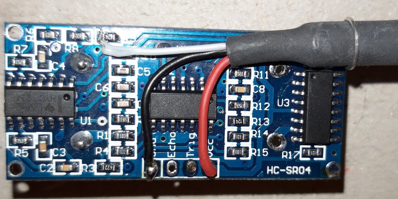
This is how the boards look like from the back
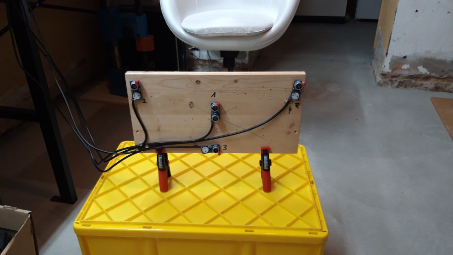
And this is the box, where all sensors will plug in.
Details on the box will follow with my next project log.
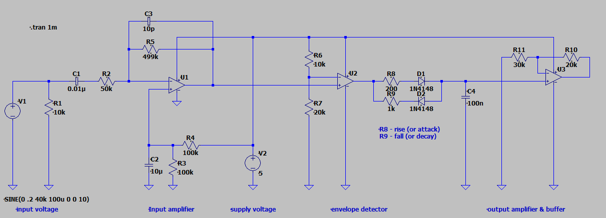
For the second version of scanner-board I did a spice simulation. (I should have done this before building the first prototype.)
The circuit has three parts:
first the input stage with input amplifier because of the small signal from the US sensor,
second a comparator / envelope detector for creating a lower-frequency signal and
third output amplifier.
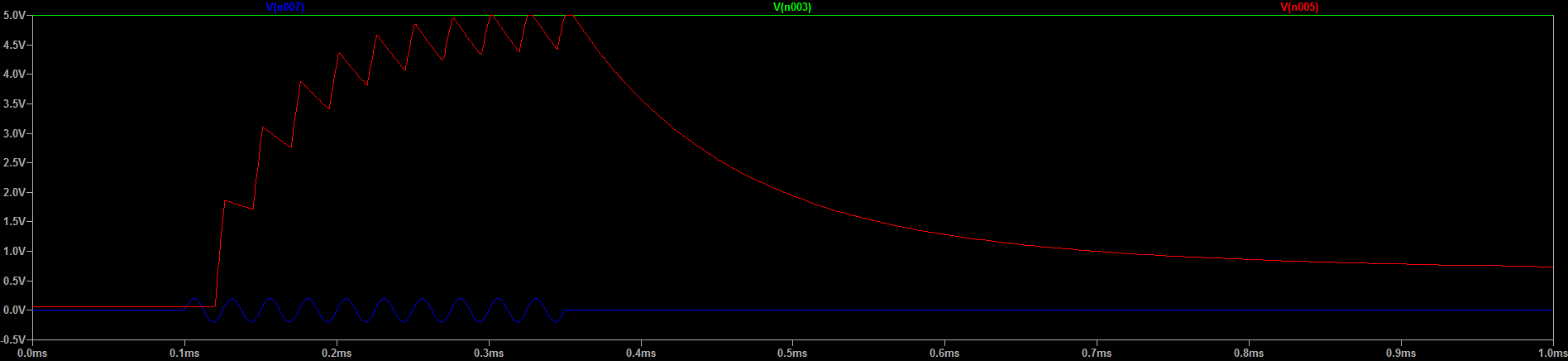
The signals: input voltage (blue) and output voltage (red)
I've read this document from TI (pdf warning) which gave me some hints for the input stage. Virtual GND for U1 is created by R3 and R4. This is necessary because I use all opamps in single-supply.
The envelope detector acts like a comparator paired with a lowpass filter. Because there is no feedback-loop U2 outputs only 0V or 5V. C4 together with resistors R8 and R9 set rise and fall time. A simple lowpass filter wouldn't do the trick since I'm interested in the peaks of the signal.
Next step will be building this circuit and testing. I'll install potentiometers for R6/R7 R8, R9 and R10/R11 to adjust the values during live-tests. Probably there will be a lot of adjusting before everything is good.
I'm excited since signal acquisition and first tests of 2D images are getting close!
A little update:
Here is the image of the signal after the preamp:
Soo, I need to eliminate all low frequencies below 50Hz. There will be another update when I created the highpass filter and the signal is clean.
Something else I think about: ~15ms may be too long for the burst. Soundwaves travel at approx. 300m/s. While sender is active, the receiver may also pick up the outgoing burst and this results in a 'dead-zone' of ~2.25 meters. (300m/s*0.015s = 4.5m). With a burst length of 3ms this dead-zone can be reduced to 0.5m.
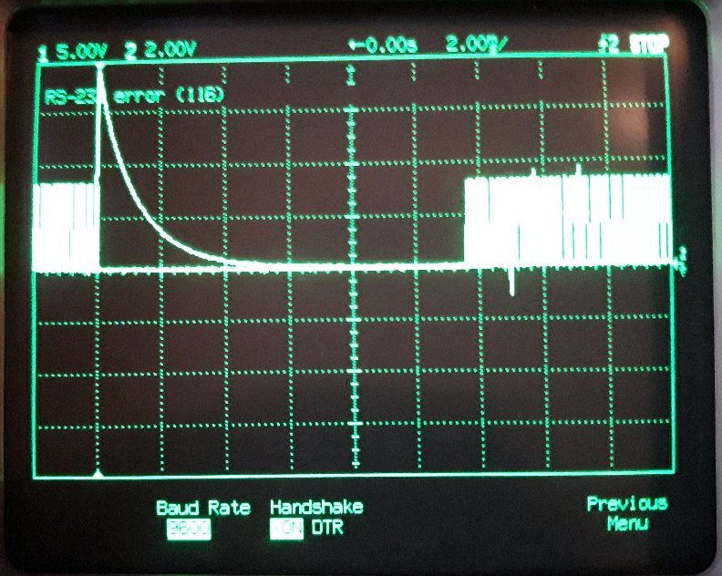
In other news: I managed to capture an image from an old HP oscilloscope via serial port. No more need for low quality screenshot-photos :)
Well, after I had some drawbacks with the scanner-board, I focused on another part of the project: the sender-board.
This device will provide an ultrasonic pulse (or burst).
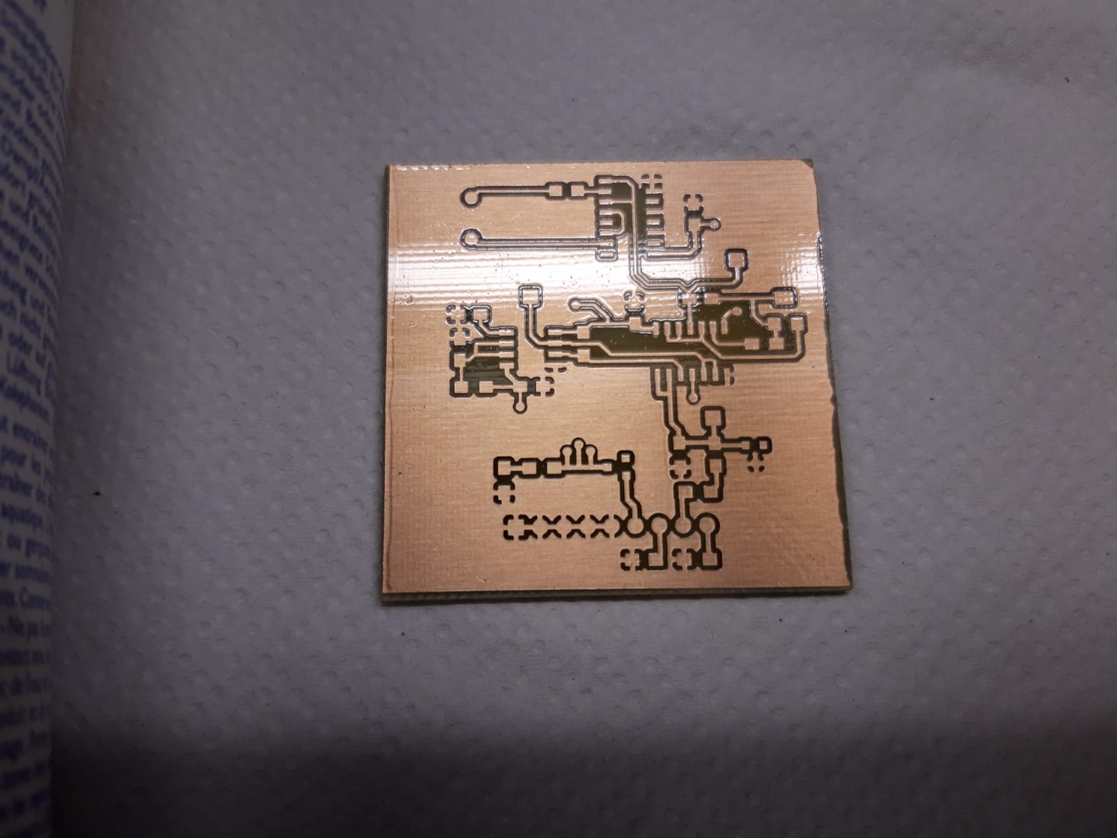
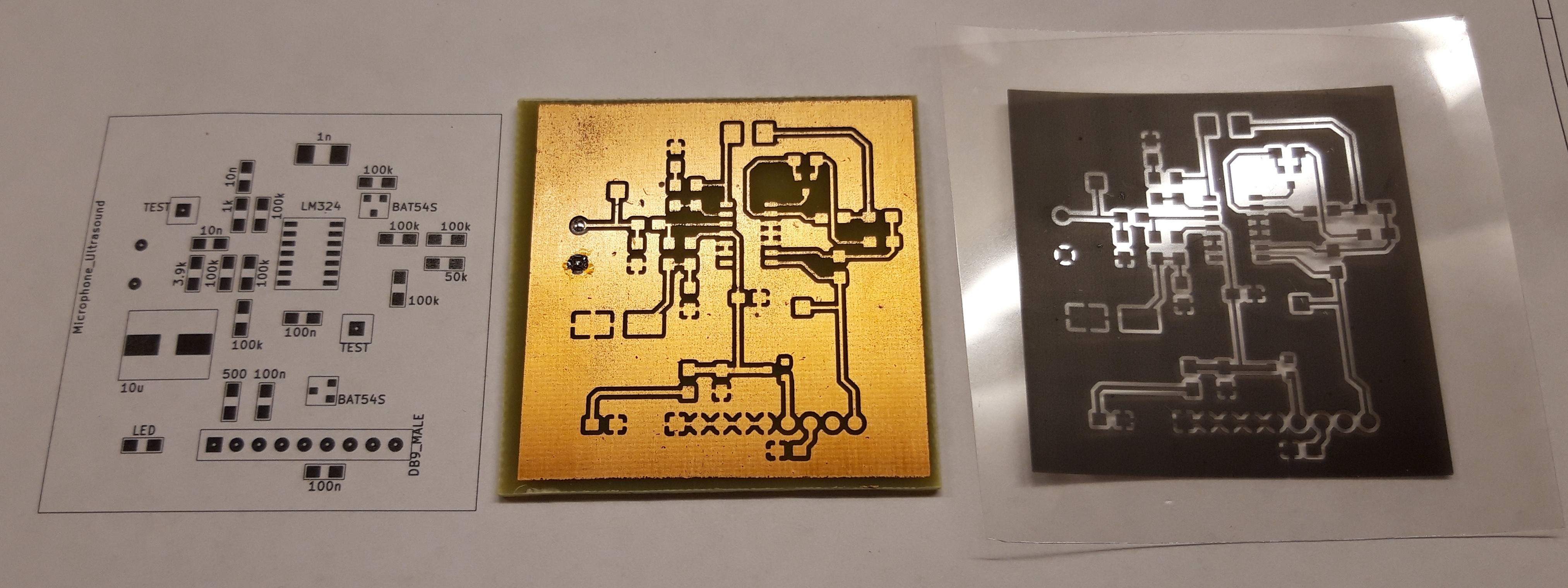
I learned some things while etching the first board, which led to great improvements for the second board.
So here we go, the board is ready for assembly:
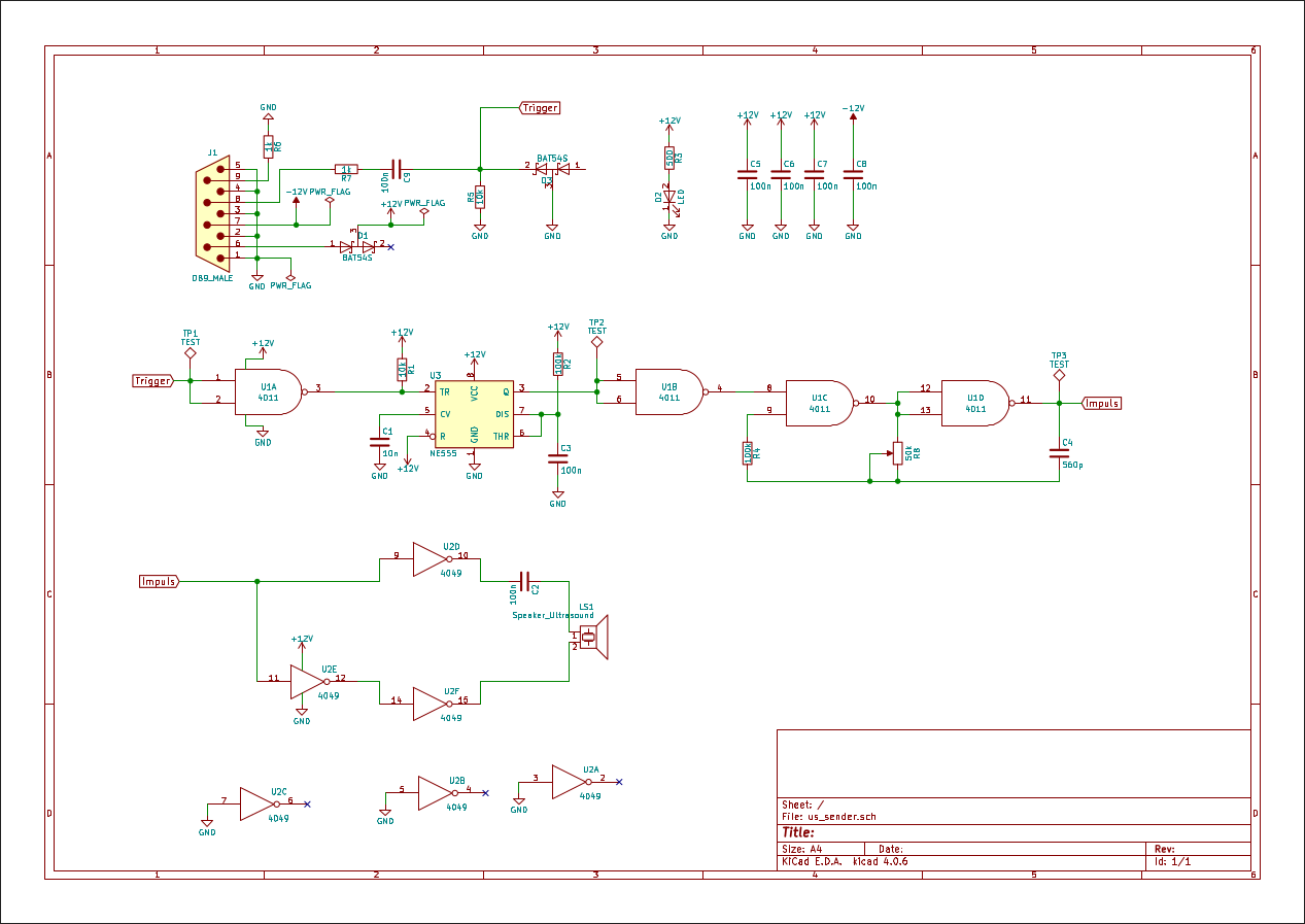
This time I first built some parts of the circuit on protoboard to test my concept and changed one or two things. So the current schematic looks like this:
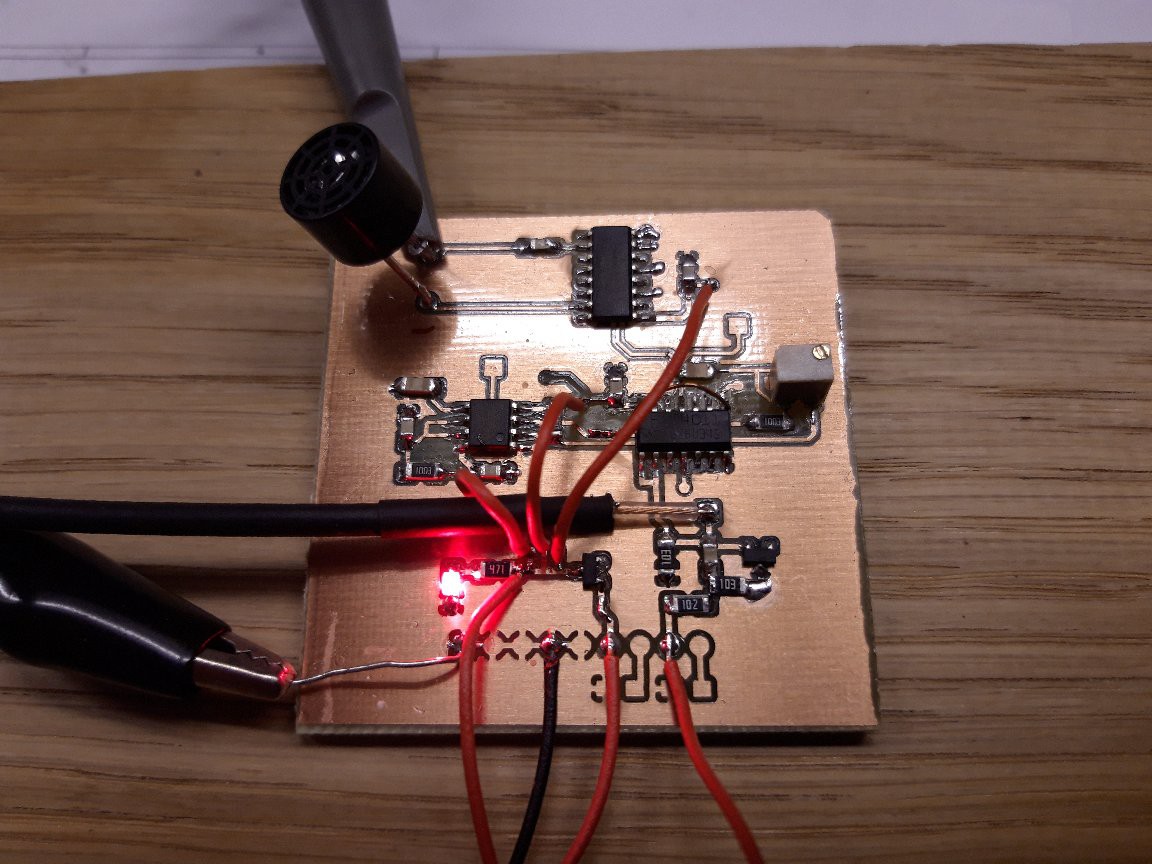
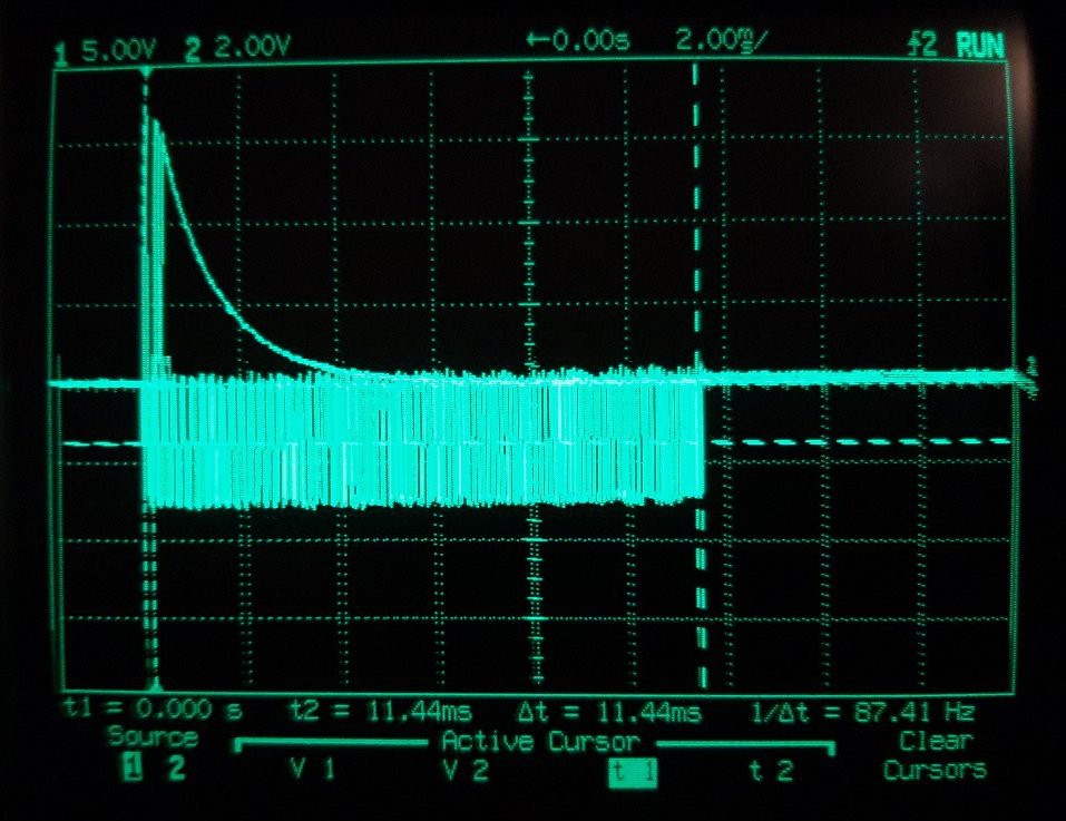
Update: Finished prototype of sender-board
Yesterday I finished the sender board.
I had to fix two things as I had the polarity of the NE555's output wrong (pulses were sent when no trigger was present, see photo below) and the TRIGGER line was missing a pull-down resistor.
After that, here is the result:
There is a BNC wire which is used to trigger the scope
The burst is now 11.44ms long. Maybe this has to be adjusted later.
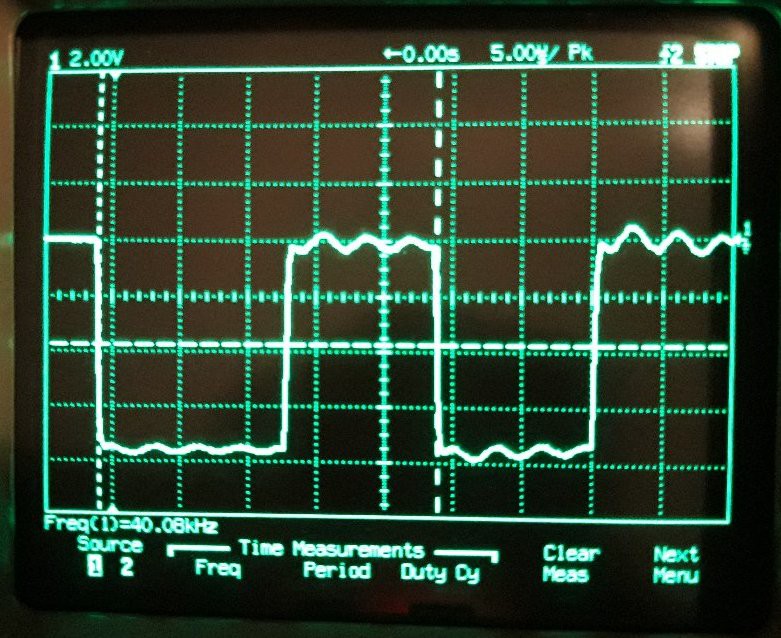
The oszcillator is set to 40.08 kHz but will surely drift in time.
Allright, summer holidays have passed, time to move on.
I started the first prototype board for the scanner, just to learn that I'm missing some parts.
So far, have a look at the board, I'v already ordered the missing parts and more images will follow.
Good news, everyone! I finished the prototype and it's - not working. It seems like I made a mistake with the power suppy for lm324 which only receives single supply but needs dual supply. All right, I'll run it through SPICE once more and we'll see what happens.
 Johannes
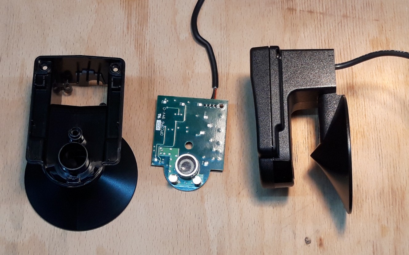
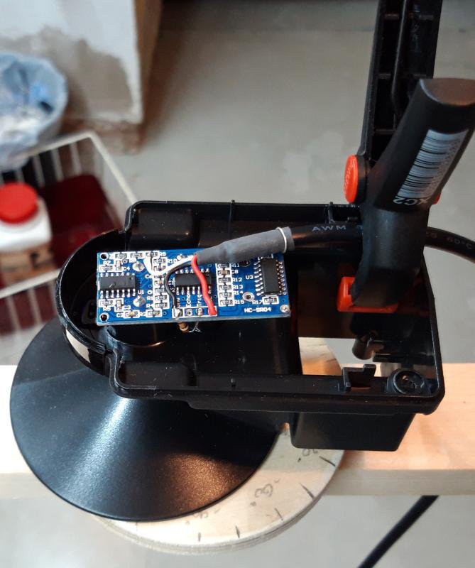 Likewise with "the cone". Here my HC-SR04 Sensor mounted inside the plastic case.
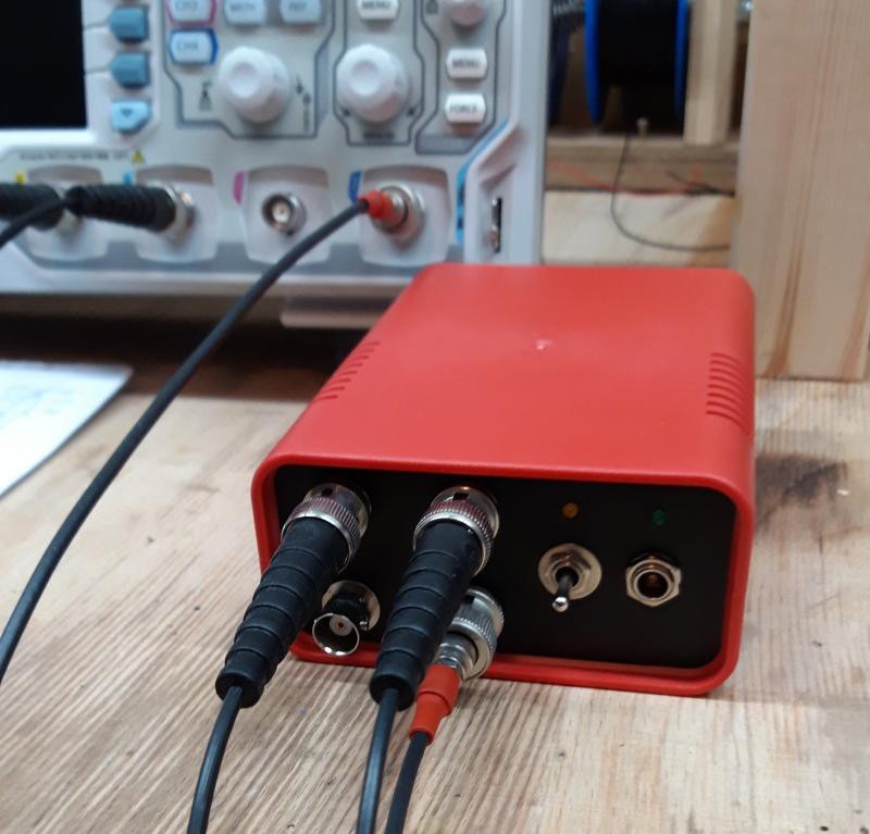
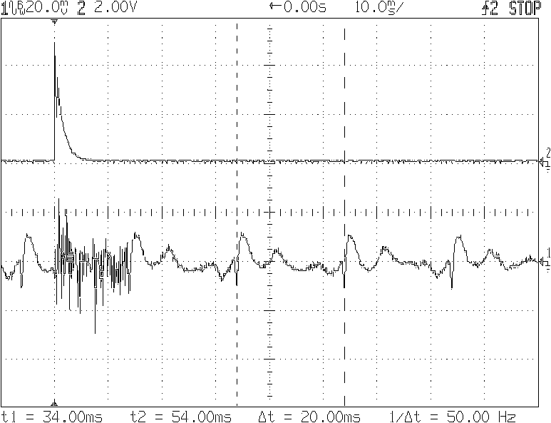 Soo, I need to eliminate all low frequencies below 50Hz.