 Mike Szczys
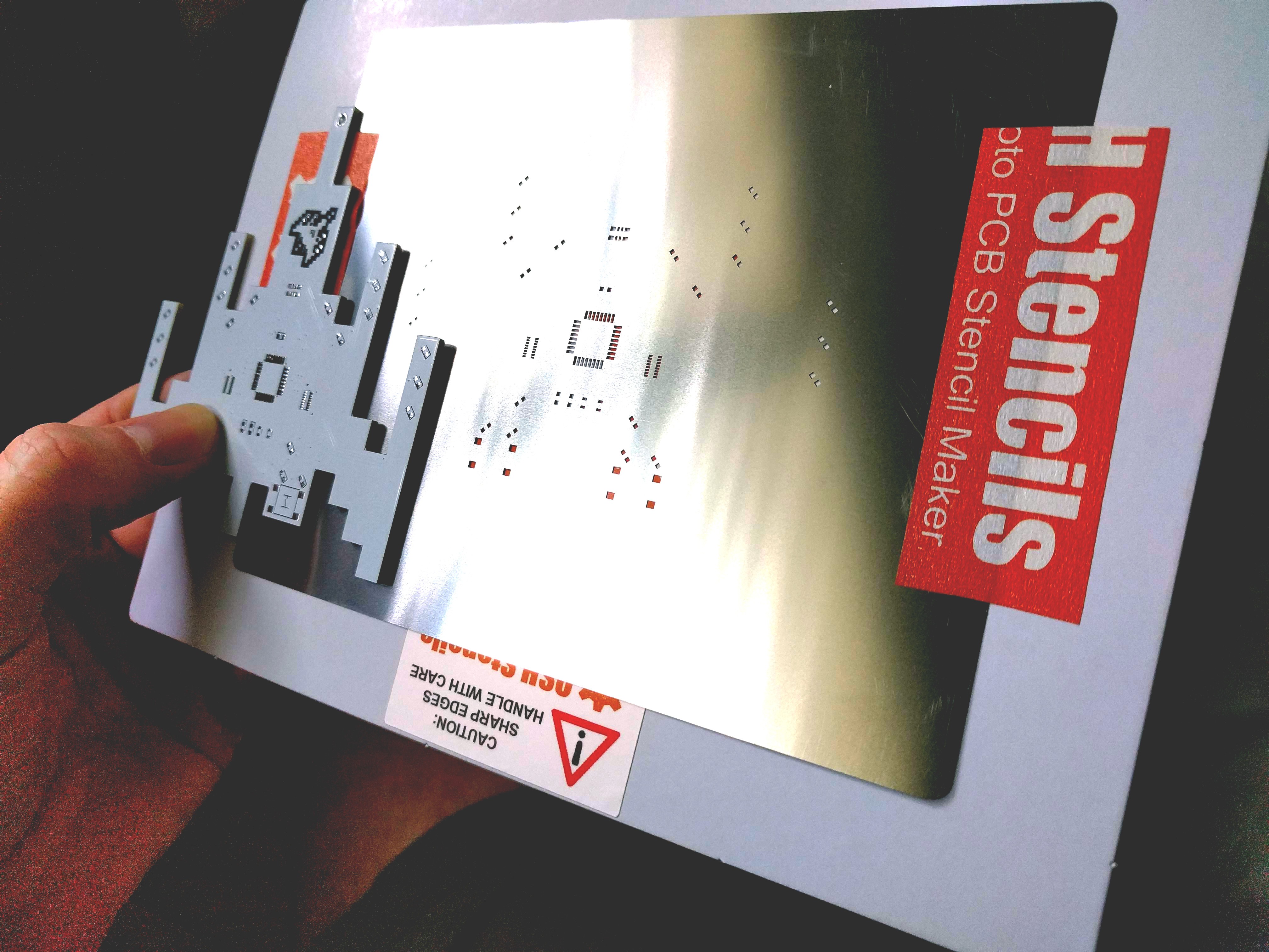
This badge would have been impossible to assemble without a solder stencil. I've never used one before and the important lesson learned is that fine-pitched components need very small openings in the solder mask. This was about $45 (delivered) so I wasn't going to order another, but unfortunately I had to rework every badge by hand to remove excess solder from the two 1506 resistor arrays (16 pins).
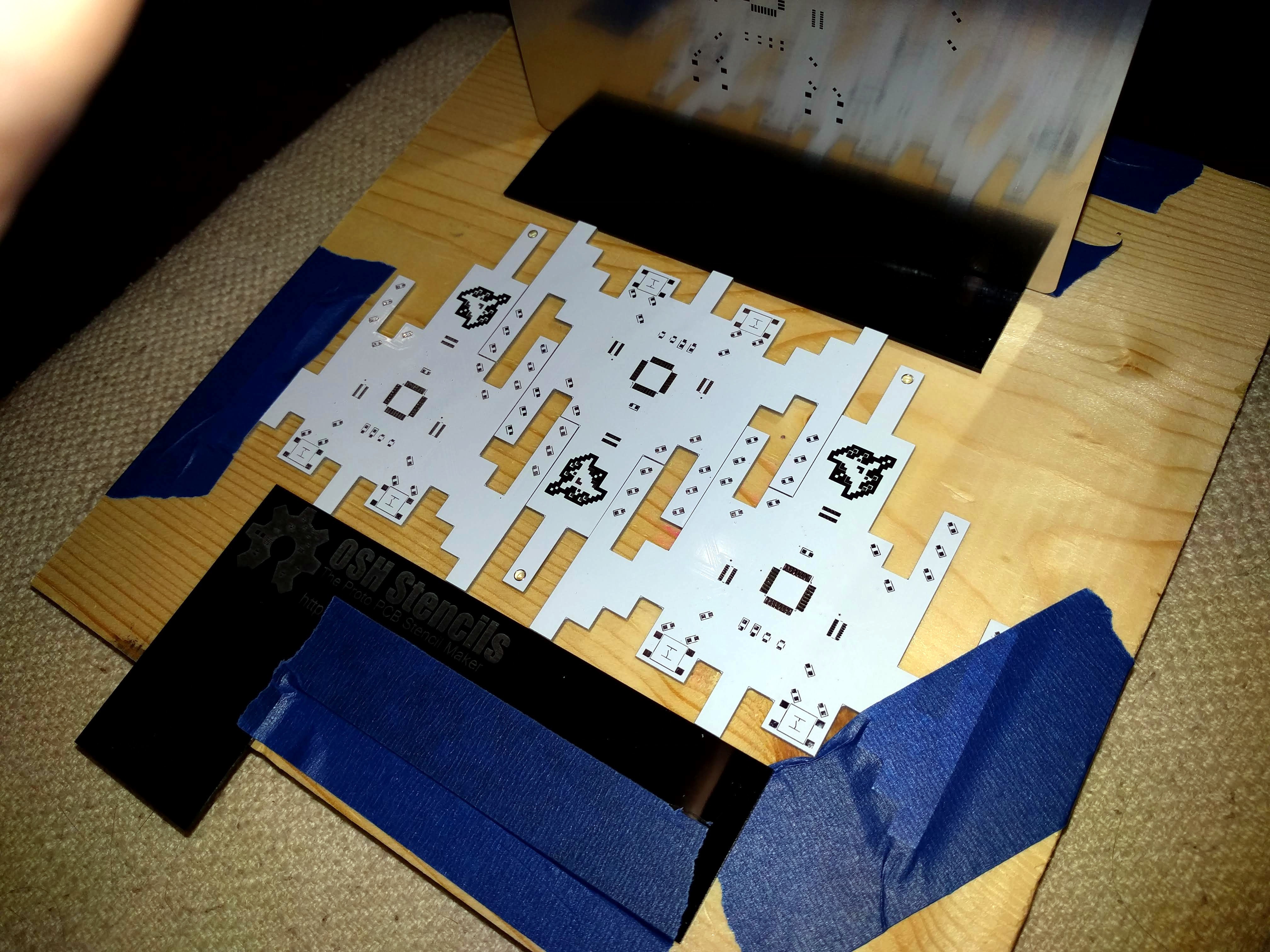
I made a little jig to use the solder stencil. This keeps it perfectly aligned with the pads on the board. Because of the odd shape of the badge I used two other PCBs as part of the jig and used a credit card (came with the stencil) as the squeegee.
Placing all of the parts was a big job. I had previously made a vacuum tweezer using an aquarium pump. You just crack it open and turn the diaphram around to make it suck instead of blowing (heh).
Here's a timelapse I made of the final four boards I assembled. You can see in the video the solder wick I used to remove excess solder that was bridging the resistor network pins.
An inexpensive toaster oven was used to reflow two of the badges at once. I set it on high, and switched from bake to broil a few times so the bottom wouldn't get too cooked. The boards were often slightly smoking by the time all of the solder flowed. I will likely add a thermocouple and some type of controller for future projects so I can get closer to a proper solder profile.
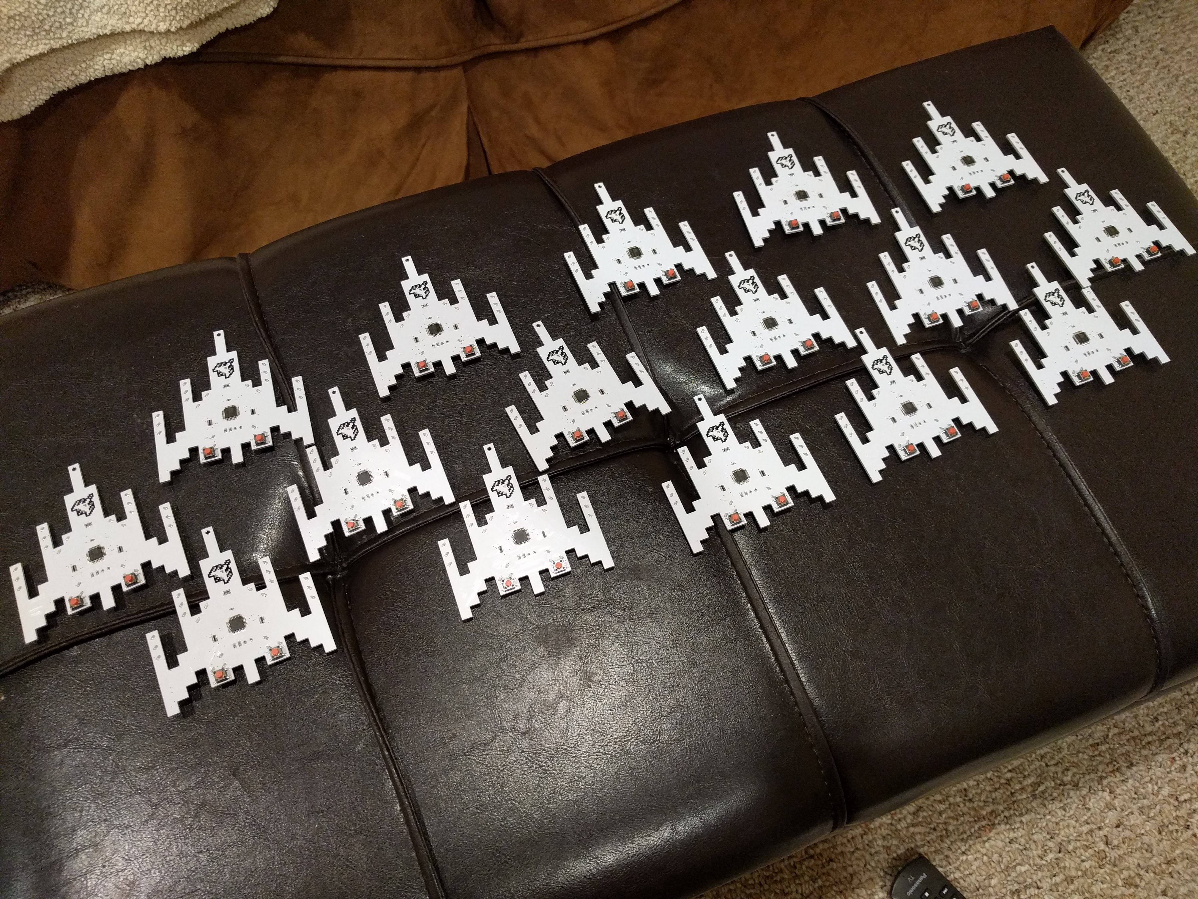
Here's the first run of 15 boards... they really turned out great!
Discussions
Become a Hackaday.io Member
Create an account to leave a comment. Already have an account? Log In.