Welcome to the first stage!
The main aim is to design the system that will generate energy while cycling. Components/tools needed:
- 1 x Stepper Motor (17HS4417). It needs 1.7A (0.85A/phase) @12-48 Vdc
- 1 x JSP XPH-4 male + female + inserts
- 4 x M3 screws
- 1 x Aluminium U channel for the Motor Bracket
- 1 x 3D-printed Spur Gear
- 1 x 3D-printed Pinion Gear
- 6 x M6 stainless steel washer
- 2 x Full-wave rectifier (2W08M)
- 1 x Electrolytic capacitor (25V, 100uF)
- 1 x DC-DC step-down converter (MP2315)
- 1 x M3 Allen Grub Screw
- Calliper or similar for measurements
- Bike - I am currently using my own bike
Nowadays, most of bikes incorporate disc brake systems, so I decided to design a spur gear to be fixed using the same screws as the brake disc and brake callipers. I chose the rear side of the bike as it is easier to modify, so I can fit the motor bracket without adding extra components. However, since I am planning to 3D print first versions, I will not be able to fix all components as tight as it needs to be. 3D printed parts may brake under high pressure.
So, I made some measurements and designed a quick prototype. Measurements depends on what is the size of your brake disc, the available space between the disc and the bike frame, and the size of the selected stepper motor.
I will use ANSI metric standard to design the gear system. In other words, both gears must have the same modulus (M), which is the selected circle pitch diameter (D) over the number of teeth (T) (figure below):
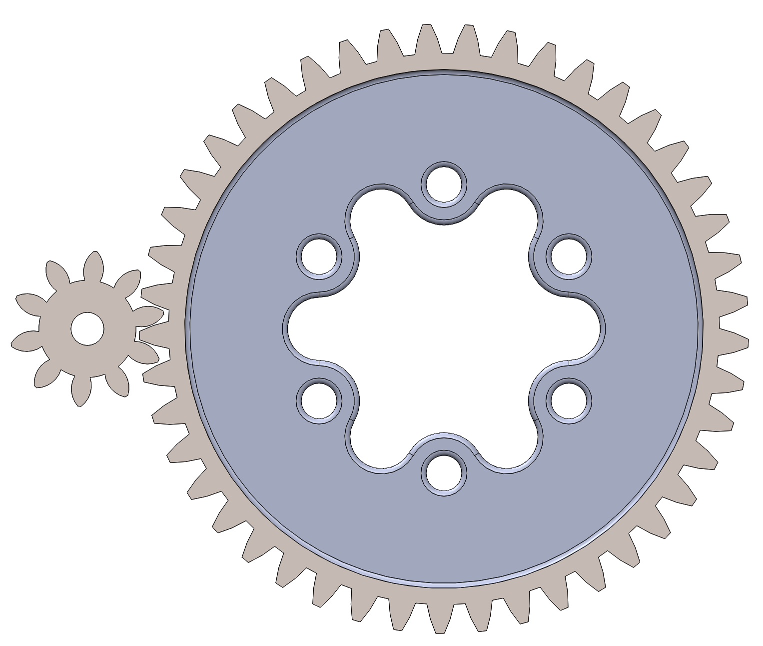
In my case I manage to obtain a gear ratio of 4.5 and have some space left so it could theoretically fit smaller break discs as there are many variations.
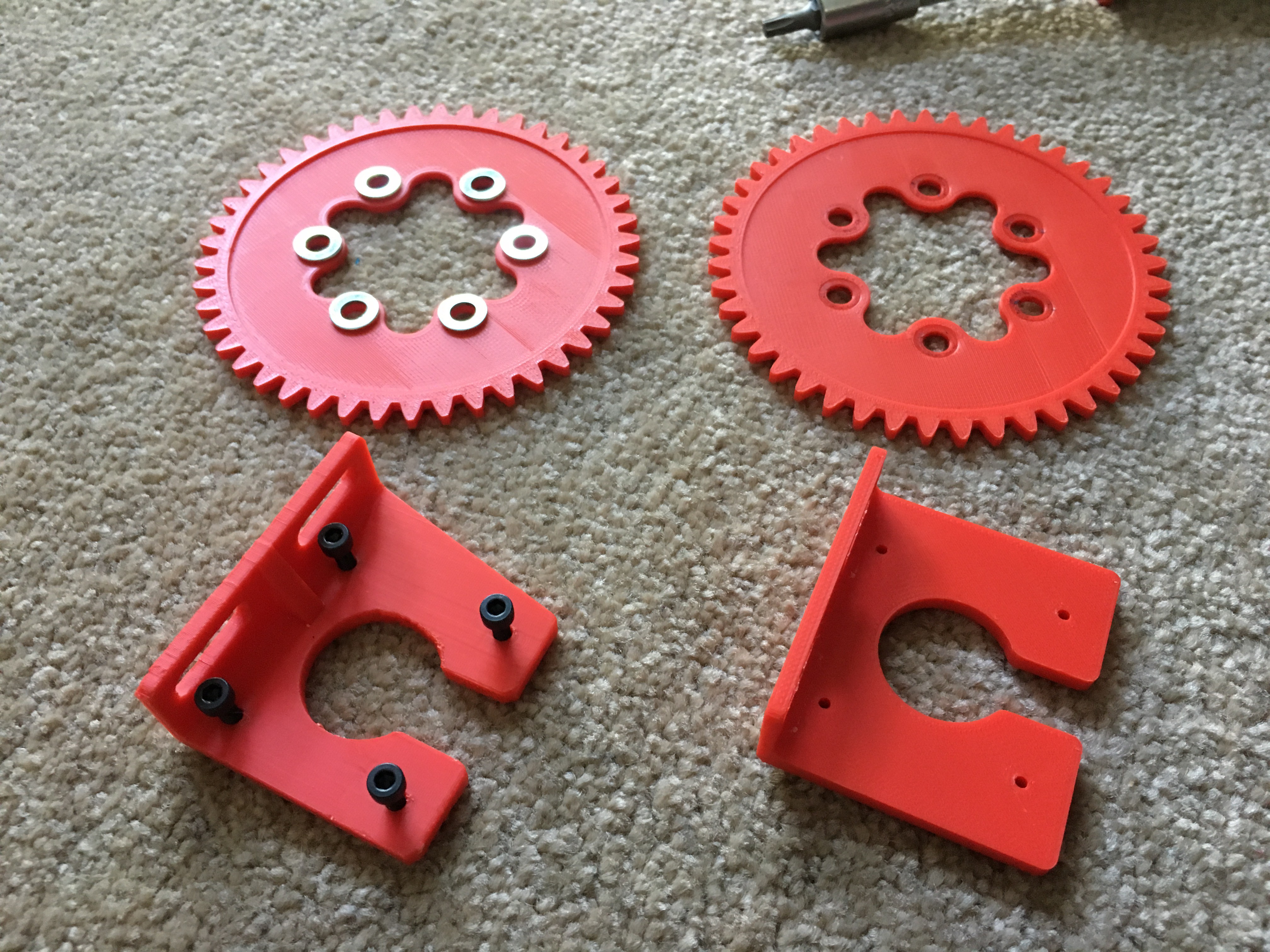
So far, I have been working on the second version. The motor bracket needed extra modifications as it needed to be reinforced with a rib. It also has been printed from one side so the filament direction will not be compromised under oscillations. The spur gear has been thickened compared to the first version and the use of washers was also very helpful.
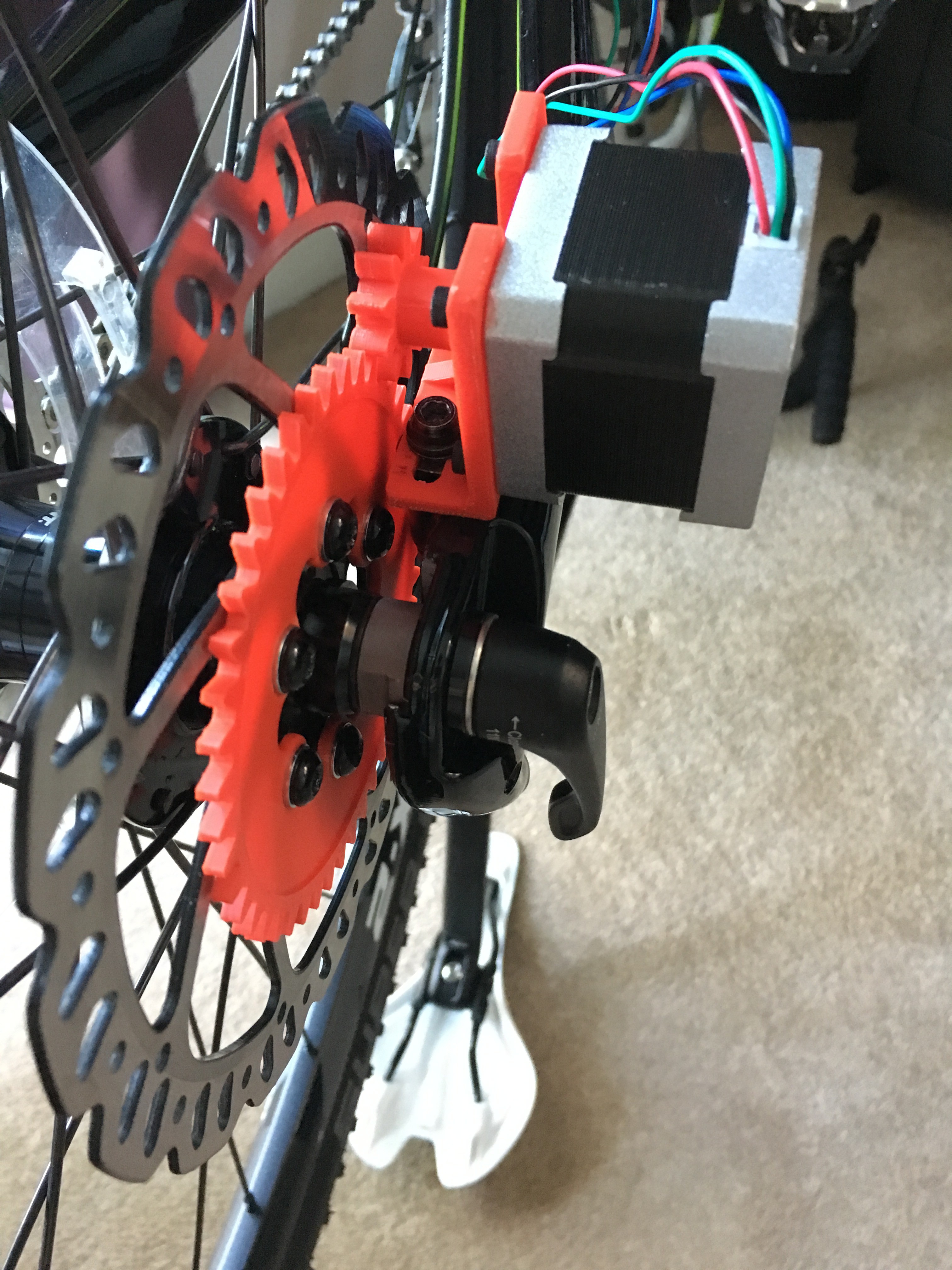
Figure below shows the previous design (right hand side) and the improved design (left hand side). I still need to go through a third version regarding the motor bracket because the motor shaft was touching the brake disc. I am sure you will notice it on the next picture.
The next step was to assemble all components. It still needs some minor modifications, but it looks promising! As I said, only four extra screws are needed to fix the motor.
I tested the system by connecting both phases of the motor in series to a capacitor, then DC/DC step down converter and a generic powerbank at the end.

Do not forget to watch the video! Unfortunately, the first time I had a 50V capacitor instead of a 25V one. I think I do not have to explain what happened to the DC/DC step down converter. However, I could still use it as a 'circuit load', so I managed to check how much current was generated. The multimeter is connected as an Ampmeter (series) after the capacitor, so as far as I know it should show the current generated at 25V (units shown are Amperes).
As it can be seen, 700mA were easily generated @25Vdc. This seems quite logical for me as each phase of the motor requires 850mA to work (I will update the video as soon as I get more DC to DC converters)
Looking forward to make more tests...on the road!!
UPDATE - 2/7/2018
Yesterday, my partner and me decided to meet some friends in London. I could not see a better chance to test what I have been working on for the last few days. Well, I did not have anything installed on the bike but the motor and gears, so I opted for a quick solution by designing a PCB and putting altogether in a plastic box.
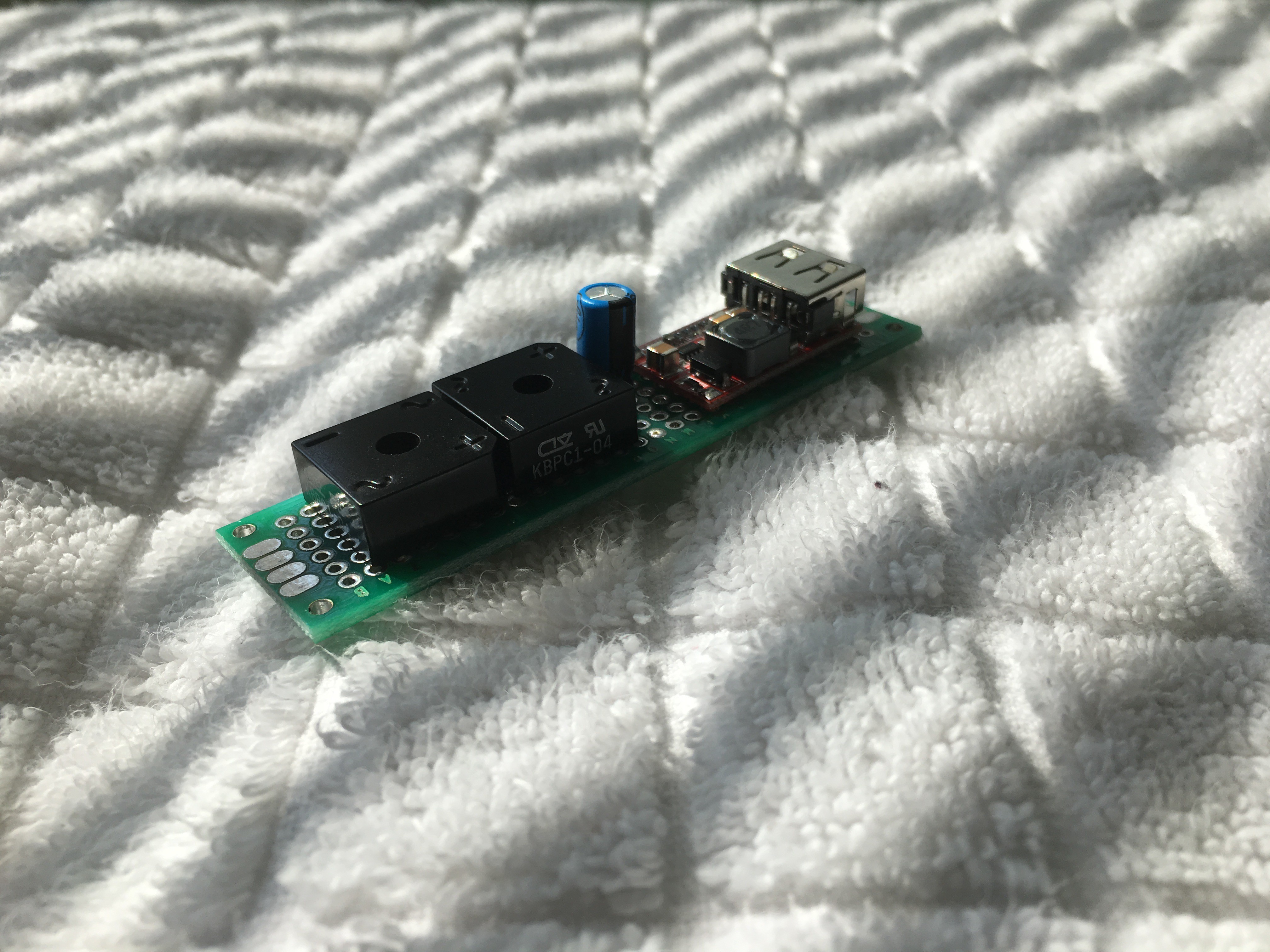
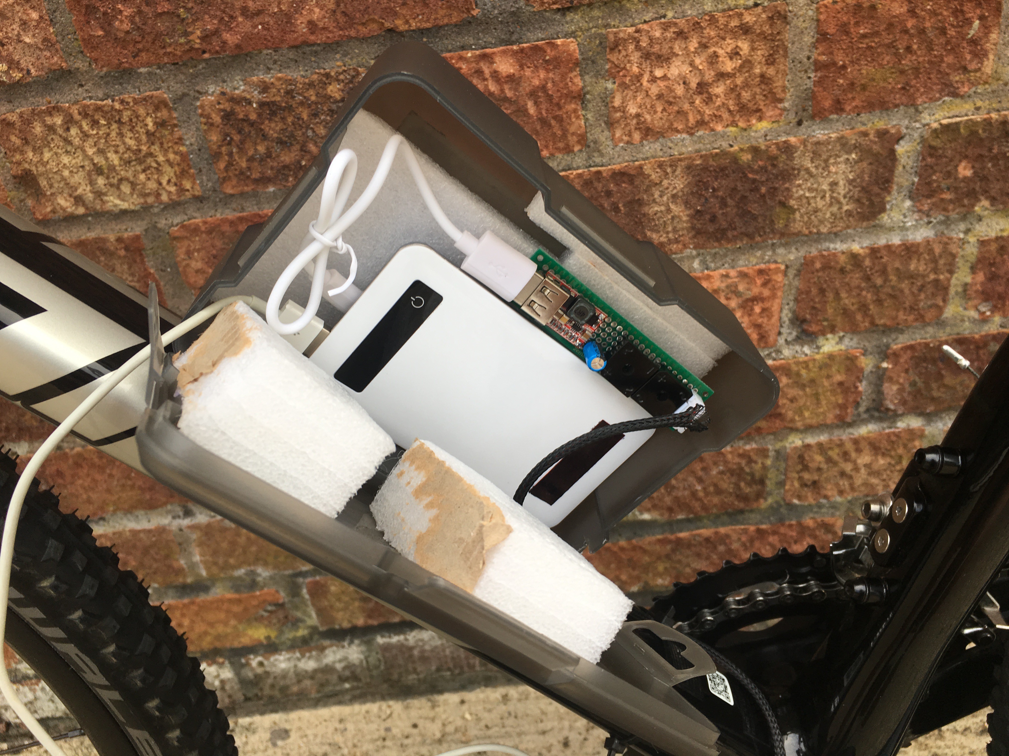
I know, I know...the box looks ugly and bulky...buuuut it is a quick and efficient solution. As you may see in the second picture, I checked the battery level on the power bank by plugging in my phone. It was dead as nothing was displayed on the screen.
Now, let me show you the bike route. First picture is Google Maps estimations and second picture is what my TomTom Runner measured. I cannot show any data regarding the energy generated as I am still working on the datalogging system.
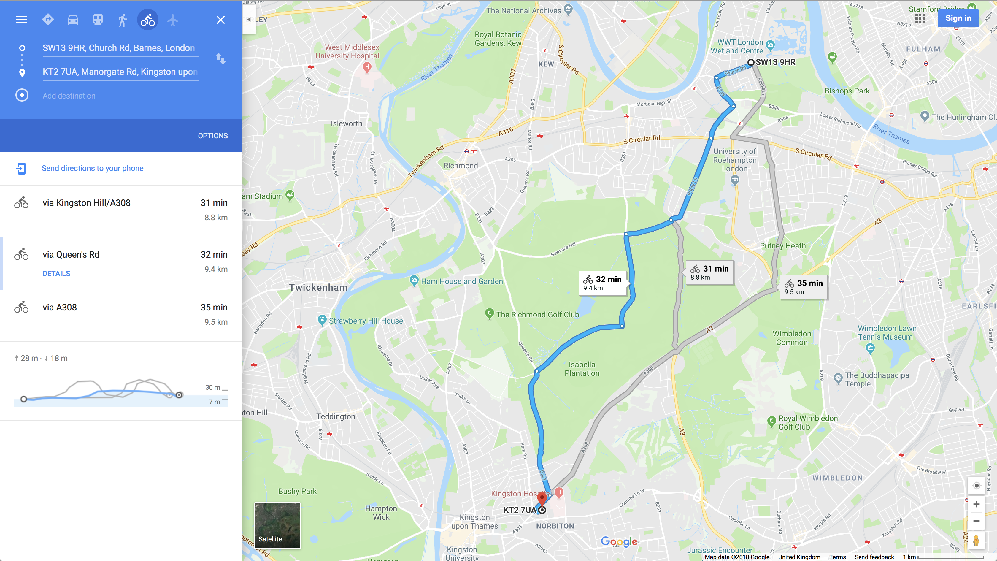
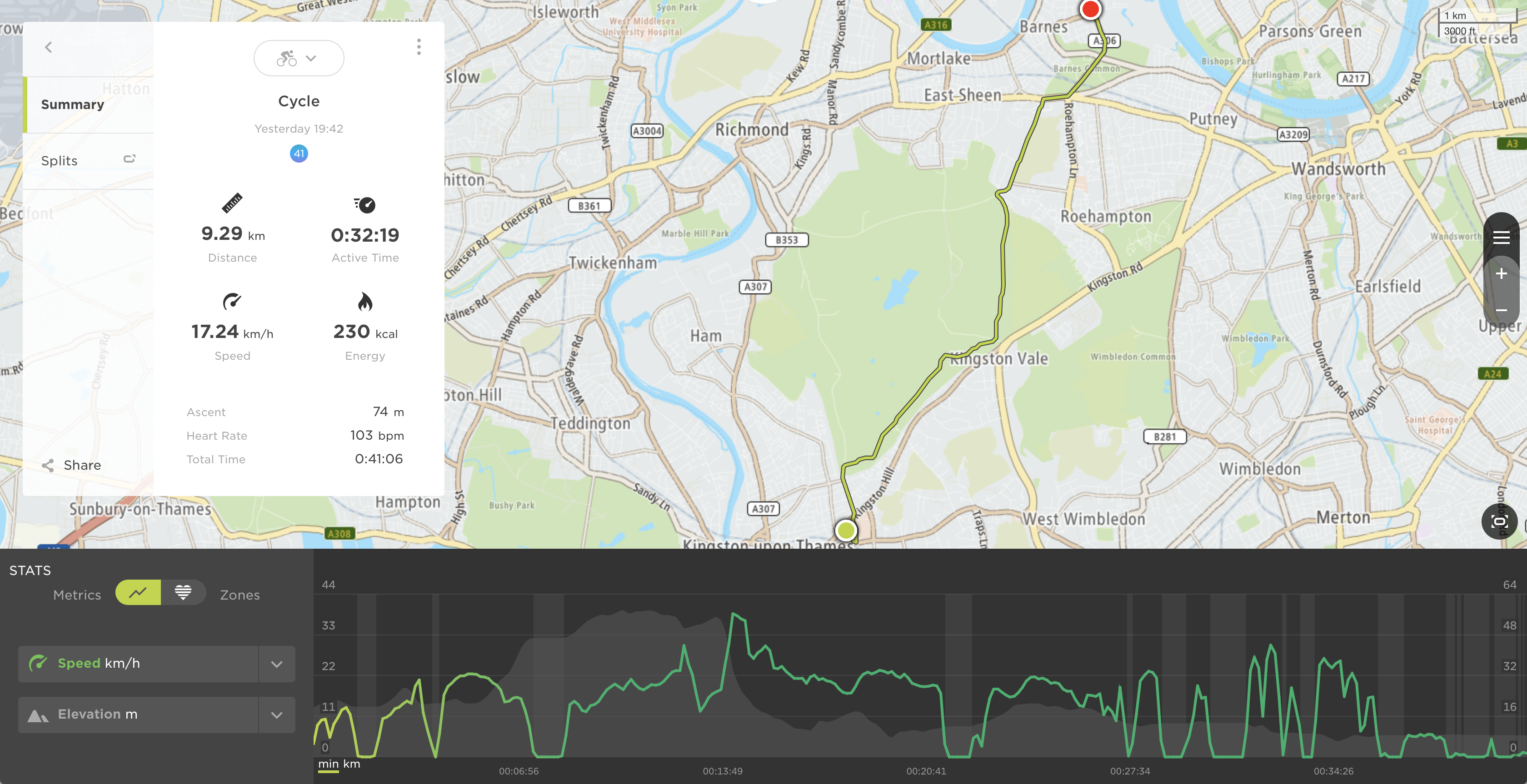
As it can be seen, I stopped several times to check that everything was working fine and we covered a total of 9.29 Km (one way) with an average speed of 17.24 Km/h. Having in mind that I had to come back, the total trip is around 20 Km in around 1 h. I made a picture of the power level when I finished and this is what I found:

It looks promising! Now, I need to work out some calculations to validate my results.
Next time, a trip with data logger!!
UPDATE - 6/7/2018
I have been commuting to work (15 min one way) whilst building the data logger system for the bike. Here are my findings having in mind that this is a prototype:
- There is evident tear and wear on 3D-printed parts, so I decided to apply some grease. As a result, no noise due to friction.
- The motor bracket is not stiff enough. Road bumps makes it oscillate (aka fatigue phenomena) and the spur gear tends to touch slightly the braking disc. I have already seen some cracks so I decided to manufacture a proper aluminium bracket.
- The stepper motor makes a very nice sound when it is spinning, like an electric car...the noise of power generation!!
- I tried to push hard these days to test the power generation stage and it gets really hot at high speeds, so I realised from the setup, that some connections were not properly made. In addition, Jurist made me realise that I had diode bridges connected in series (higher voltage) rather than in parallel (higher current). Again, I am still building the data logger system and still cannot upload results, but I was able to generate 1A@16V (16W).
Let's keep pushing hard...
Q&A Section
Can I use different stepper motors?
Yes you can, but bear in mind that your circuits may need to be redesigned and you may also start experiencing some drag if a powerful motor is chosen.
How can I identify phases in a bipolar stepper motor?
Grab a multimeter and switch it to resistance measurement mode. Now take two random cables and measure its resistance. If those cables are part of a coil, they must show a resistance value (value depends on the motor size).
 Javier Betancor
Discussions
Become a Hackaday.io Member
Create an account to leave a comment. Already have an account? Log In.
Hi Jurist!
Sorry for the late reply. Busy days around here...
I am glad you are reading the post!
Actually, you made me realise that I made a mistake! With the gear system I can generate very high voltages easily when connecting both phases in series. My initial idea was to have a high voltage and the step-down DC converter would do the rest of the job (high voltages and low current like power lines). As I bought very cheap ones, ranges are limited and I literally blown up one of the converters. Also, diode bridges get really hot after pushing the bike. I am building a proper circuit right now.
In other words, thanks to your comment I decided to connect both diode bridges in parallel. I was easily generating 1A@16V (16W) at a normal speeds. I know I will not be able to generate more than 1.2A but I think it is already a big improvement. I will tell you soon if I notice the drag while cycling, but so far I cannot feel it.
Regarding your solution, I would give it a go. Just to check if it really affects the efficiency. From a basic setup you should be able to test and identify which component needs to be replaced. If you need help let me know!
Are you sure? yes | no
Connecting windings in series is nice hack.( I guess, 2x higher voltage on motor windings still is lower than absolute maximum ratings for insulation breakdown voltage.)
When I thought about making something similar for my bike, it was rectification of motors phase voltages with Schottky diode bridge, passing to bulk capacitor and then passing to step-down dc-dc / charger / whatwever load. (I guess, this option maybe smaller efficiency, due to extra lossed on diodes)
Are you sure? yes | no