 Javier Betancor
I am back! Yes, it has been a while. I have been travelling for a conference and I have been preparing my presentation, some paperwork and finishing other projects. It was amazing!!
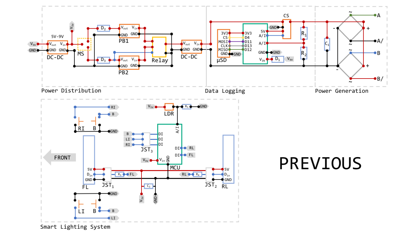
Coming back to the main subject, I know I did not explain much in the eBox Stage log entry, but it is mainly because I decided to upgrade the initial design. Both images are shown below, so both designs can be easily compared. Components needed for this stage are:
- 1 x 3D-printed eBox assembly
- 2 x 3D-printed Power Bank Housing
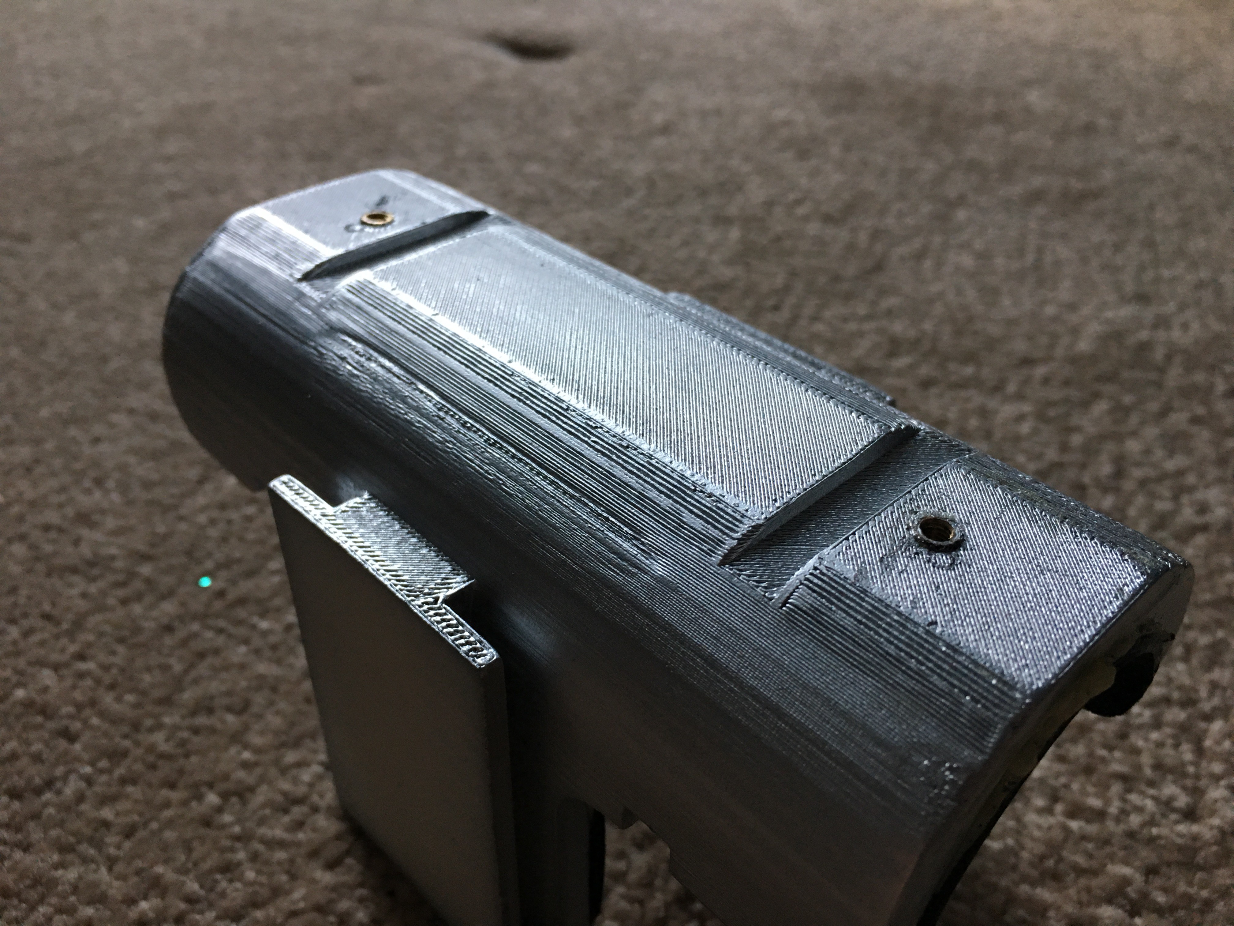
- 1 x 3D-printed eBox Mounting Bracket
- 1 x Strip Board
- 1 x Relay (SRD-05VDC-SL-C)
- 2 x Diodes (1N4007)
- 2 x USB 2.0 to Micro USB cable (1m)
- 2 x Power bank
- 1 x Single Solid Core (SSC) Black wire (0.6mmx1m)
- 1 x SSC Red wire (0.6mmx1m)
- 1 x SSC Green wire (0.6mmx1m)
- 1 x SSC Yellow wire (0.6mmx1m)
- 1 x SSC Orange wire (0.6mmx1m)
- 1 x SSC Purple wire (0.6mmx1m)
- 2 x M3 screw
- 1 x Rubber Sheet (250x250x1.5mm)
- 2 x M3 Threaded brass insert
- 8 x Neodynium Magnet Disc (3x20mm)
- 1 x Stainless Steel Rod Bar (200x2mm)
- 2 x Blue LED
- 2 x 220Ohm Resistor
- 1 x DPDT Switch
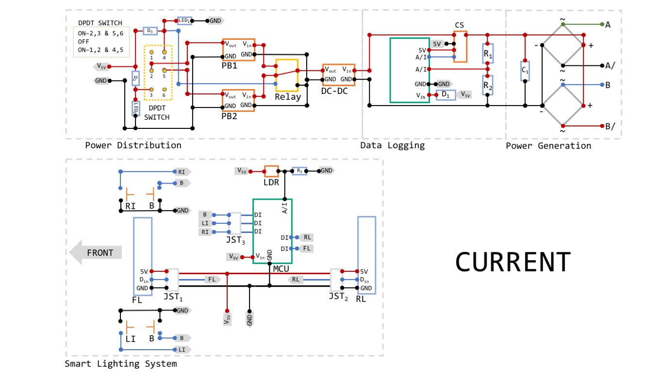
Please find all changes listed below:
- FireBeetle (ESP32) instead of Arduino Nano v3
- 5V to 9V DC converter is removed
- C2, R3 and R4 are removed
- There was a bug in the relay connection that keeps the coil active permanently. With a Double Position Double Throw (DPDT) switch, this problem is solved.
- LED1 and LED2 have been added, so the user can see which power bank is being used to provide energy to the system
The addition of the ESP32 brings some advantages to the system:
- An improved processor - there is no need of using two MCUs
- BLE connectivity - the uSD module is removed and now all data is directly streamed to your phone
- OTA (Over The Air) updates
- Blynk App is used while you ride like a dashboard, where different commands can be executed, the generated power is directly shown and the linear speed is acquired from your phone GPS and displayed too. (You will be able to download and modify my program, so anything is possible!)
- There is no need of installing a DC-DC step-up converter. Everything works within 5V.
As a remainder, I would like to clarify abbreviations shown in previous pictures:
- D stands for 'Diode'. Diodes used are 1N4007
- R stands for 'Resistor'. R1 is 1KOhm, R2 is 120Ohm and R5 is 10KOhm
- FL stands for 'Front Light'
- RL stands for 'Rear Light'
- RI stands for 'Right Indicator'
- LI stands for 'Left Indicator'
- B stands for 'Brake'
- The relay used is a SRD-05VDC-SL-C
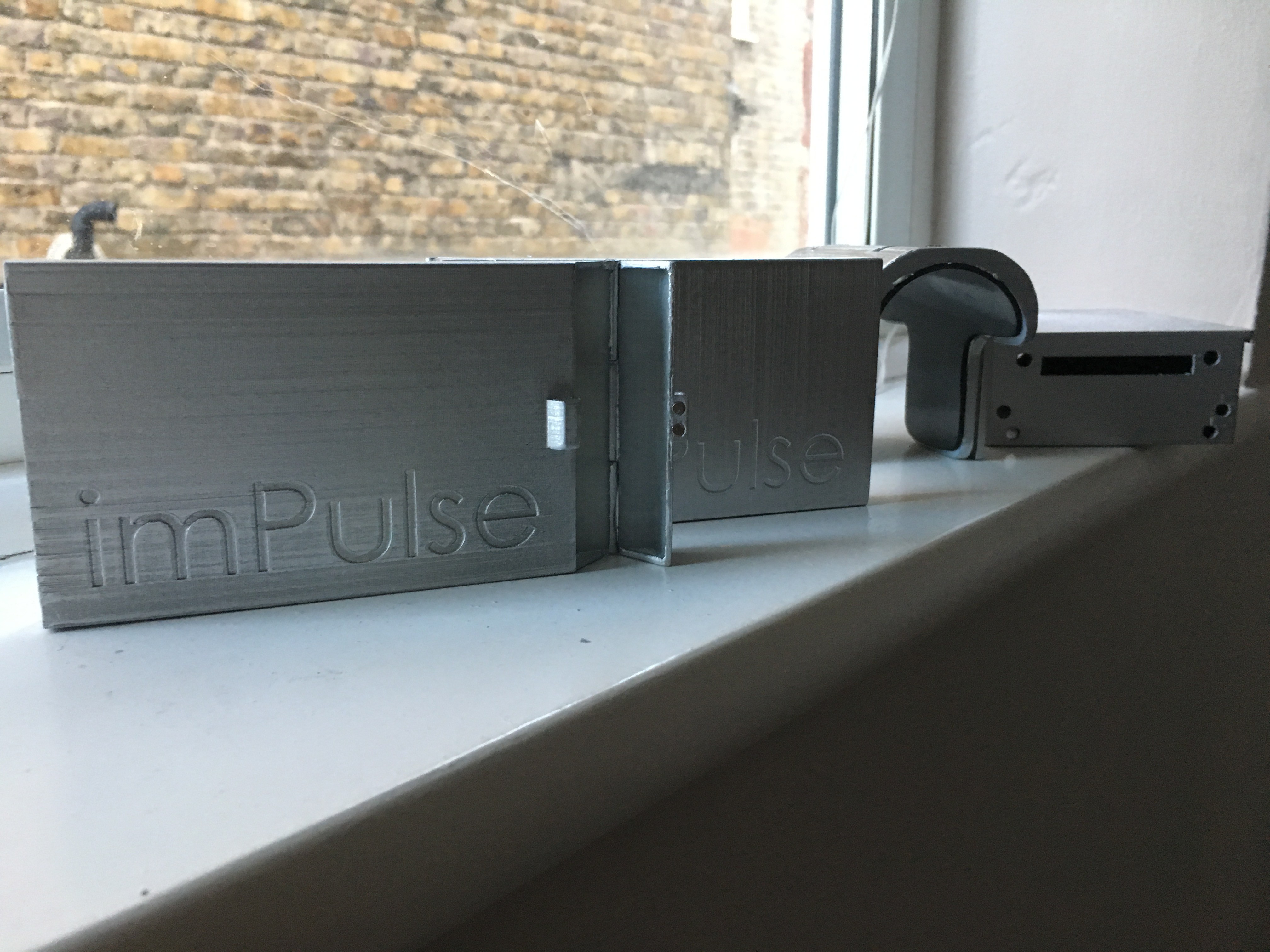
And....real pictures!!

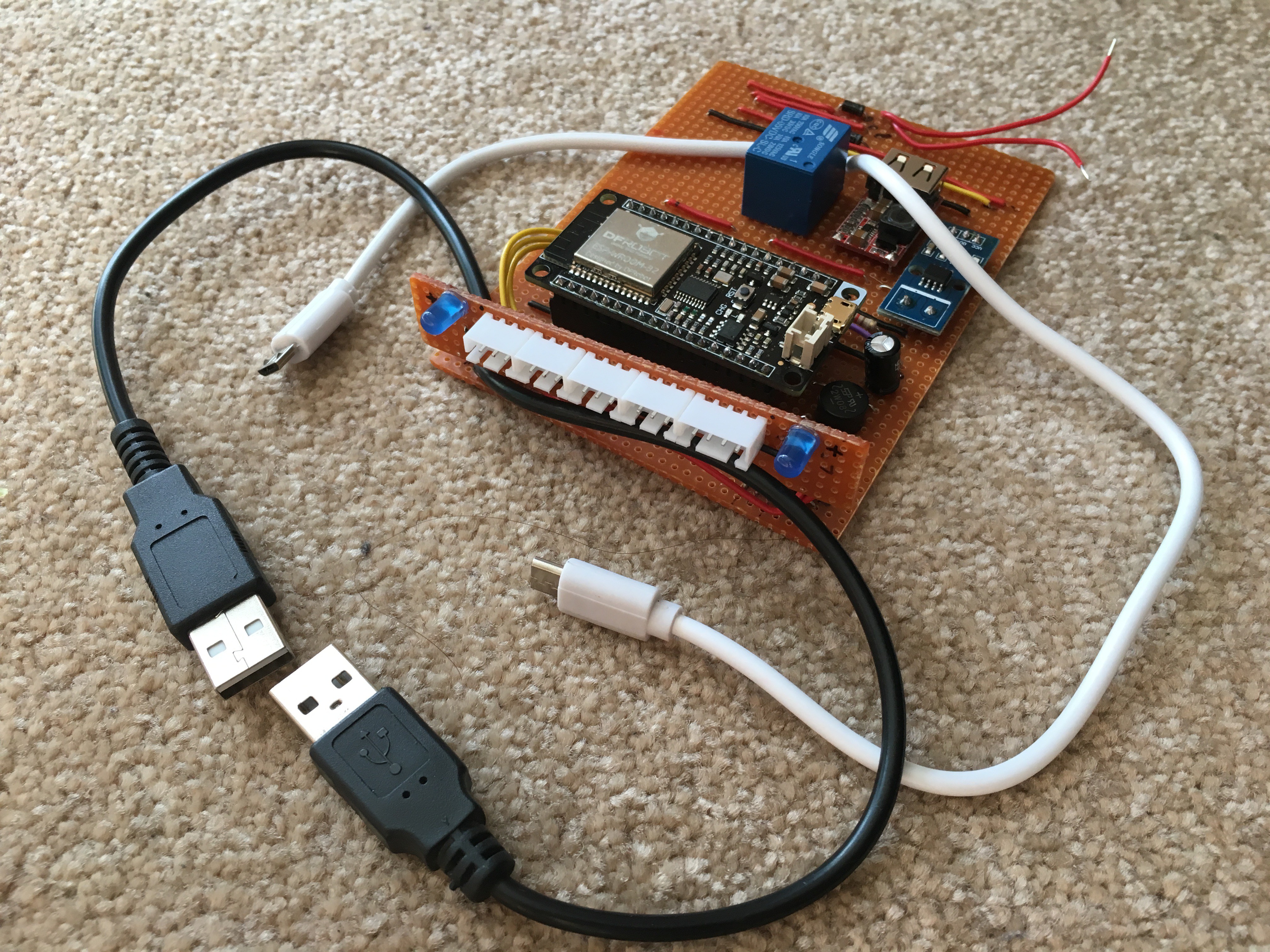
I also have to say thatI am looking for hardware bugs as everything seems to be perfect in the diagram (like the relay bug).
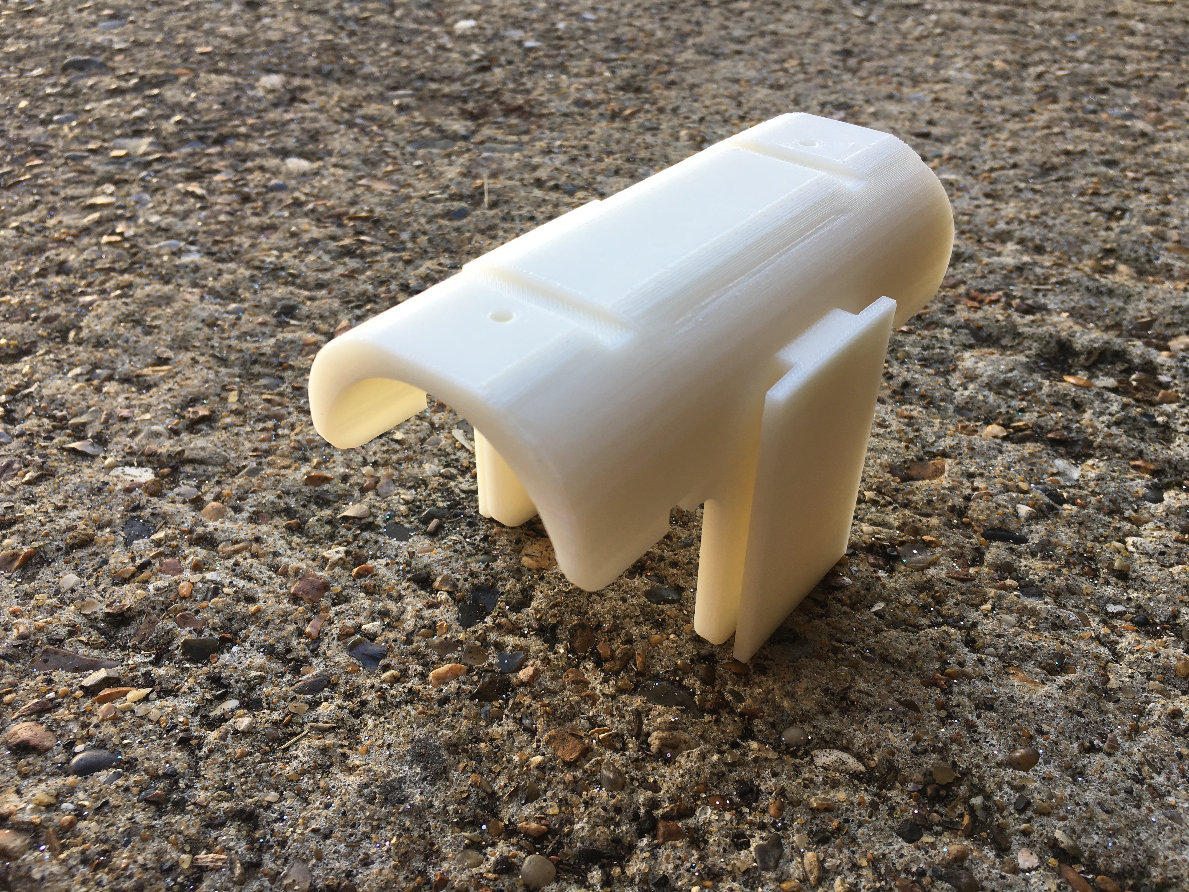
Regarding the eBox design, I mentioned that I wanted to leave the bottle cage mounting point for its purpose and I managed to do it. Below you will find the CAD (models uploaded asap) of the assembly which has four components and is modular:
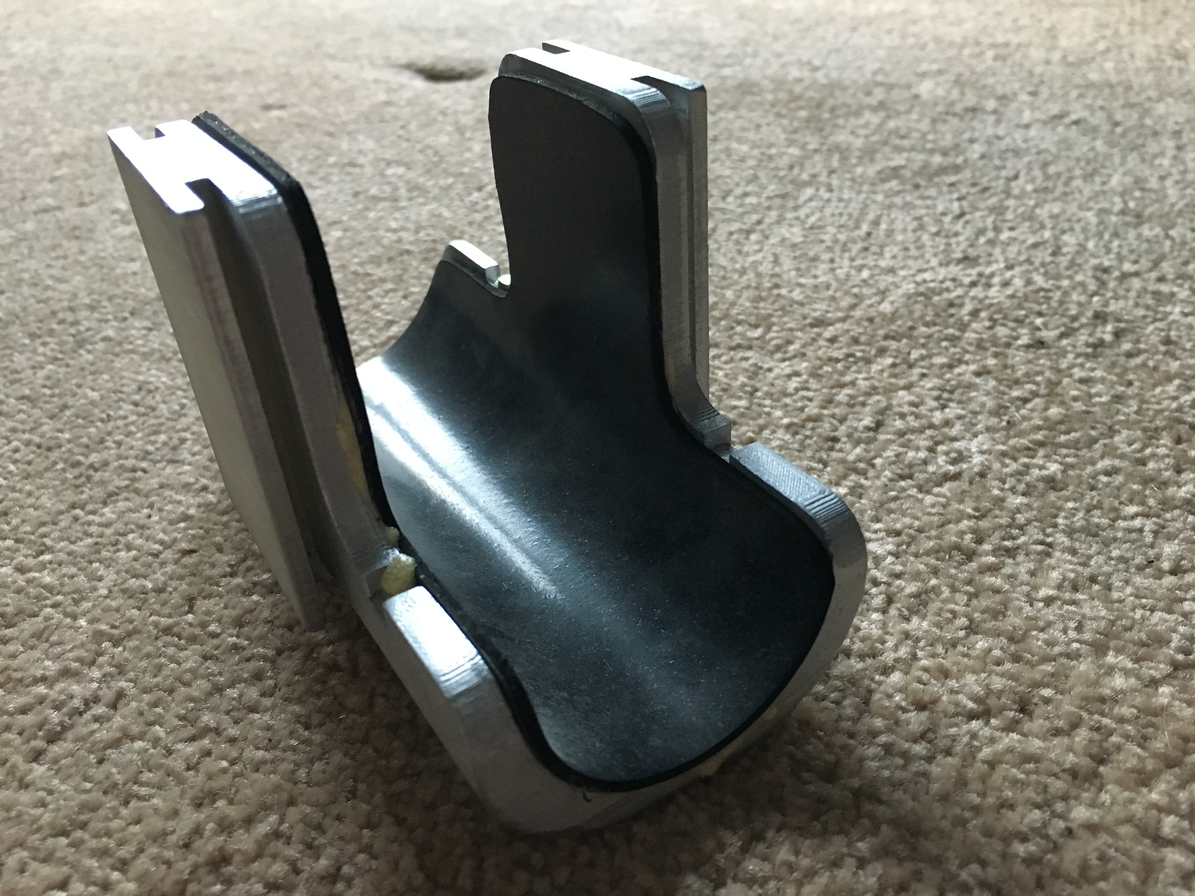
- An adaptor for the bike main frame that holds all parts together and makes the system just one part that can be easily removed for cleaning purposes. This is the only part that changes depending on your bike and is located right after the steering wheel keeping other mounting points free!
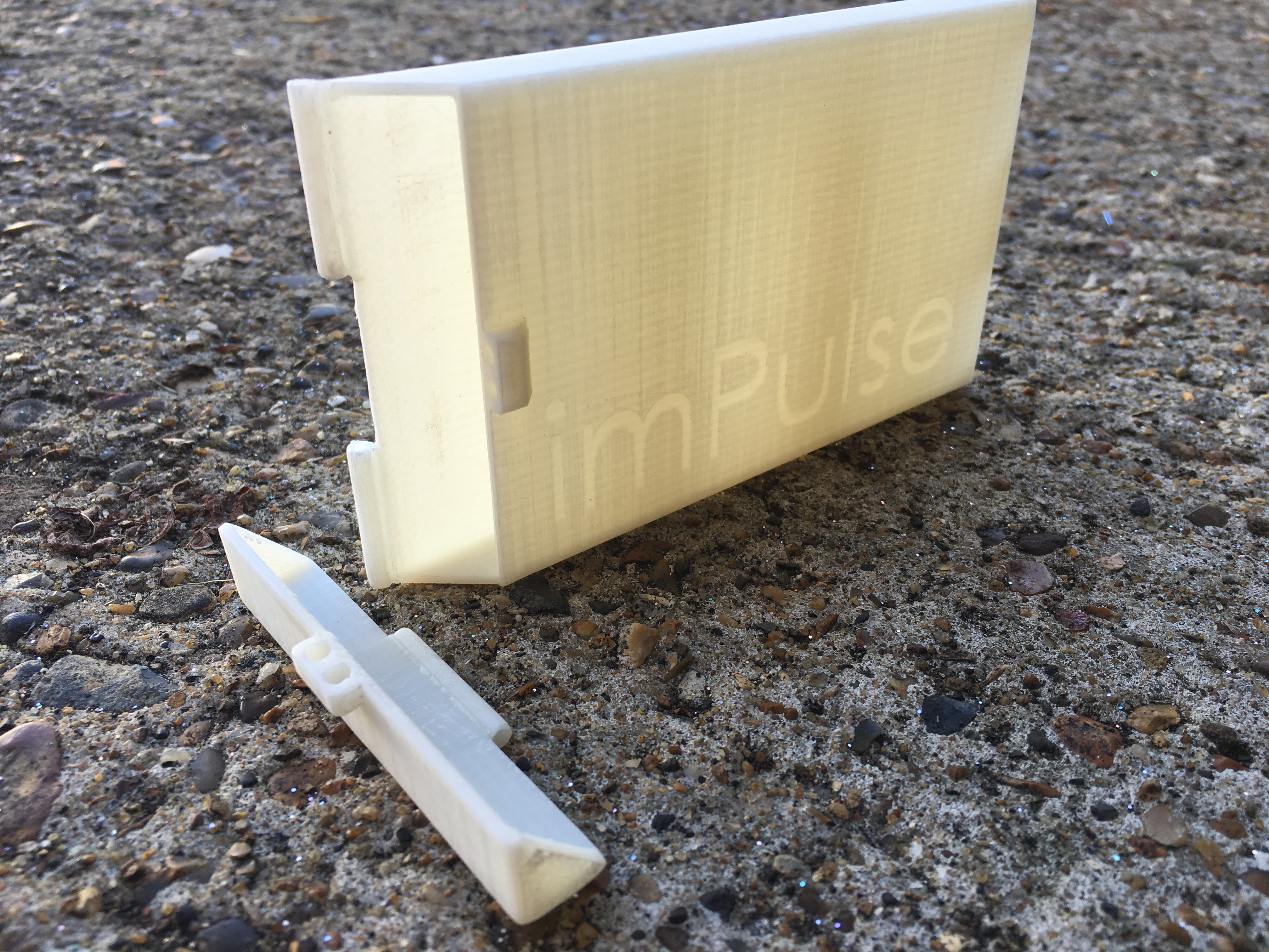
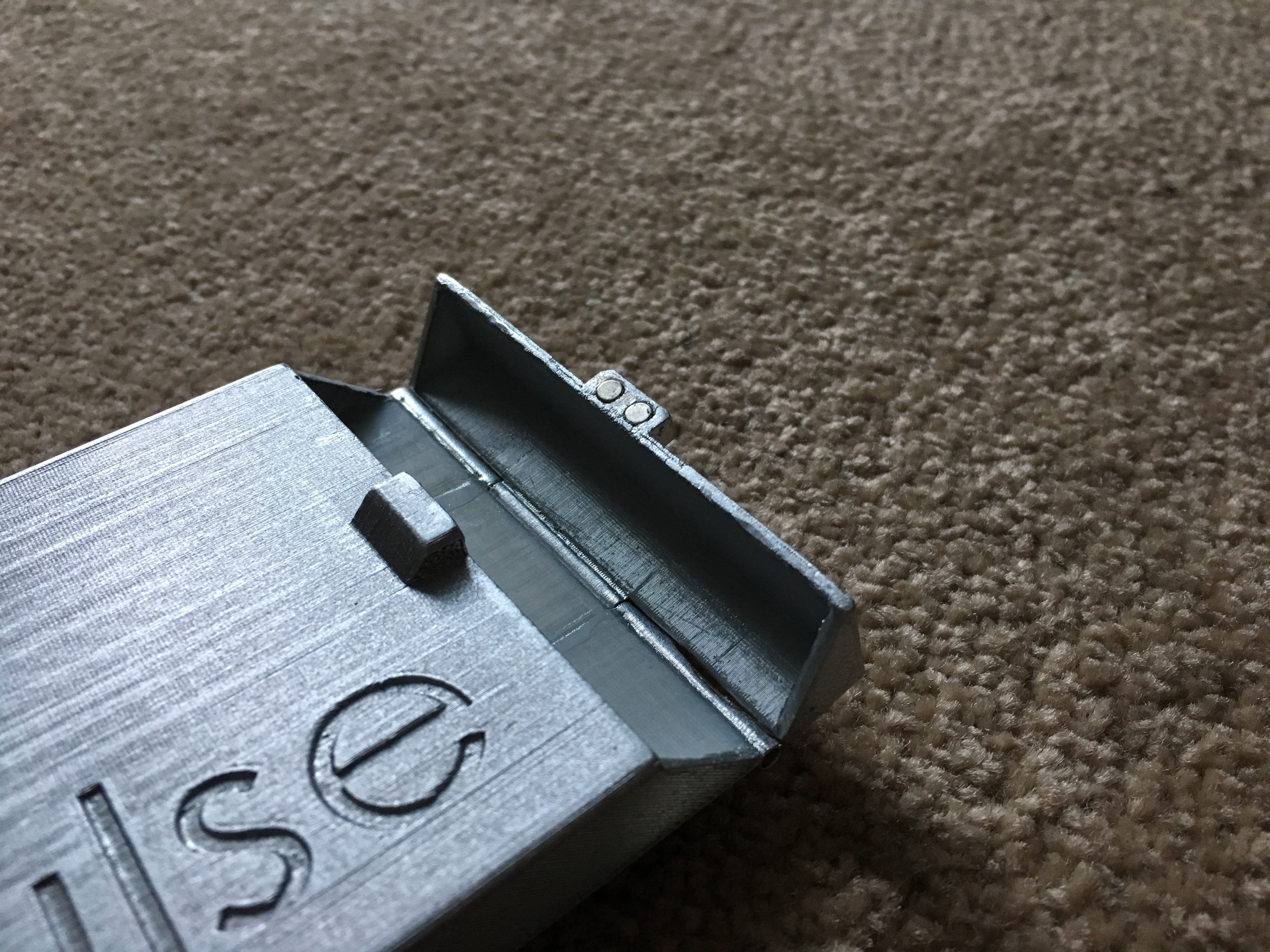
- Two power bank containers - you can also decide if you prefer to charge your phone instead! It only needs to have a T-slot, so give wings to your imagination! This containers can be opened/closed at any time as they have a magnetic mechanism (I really like magnetism!)
- The bECU (eBox) is fixed using screws on top of the adaptor.
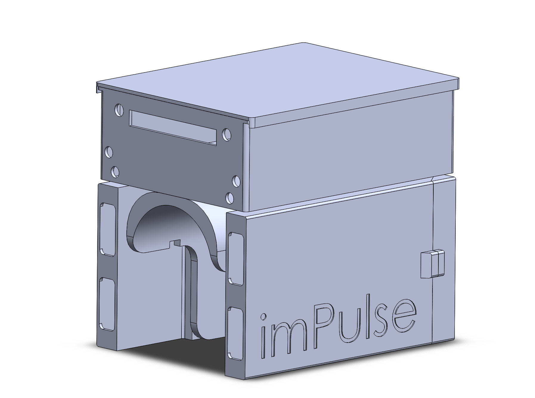
Unfortunately, due to the time being I could not design a waterproof system, but I have it in mind for future releases! Now, let's jump to the real world again:

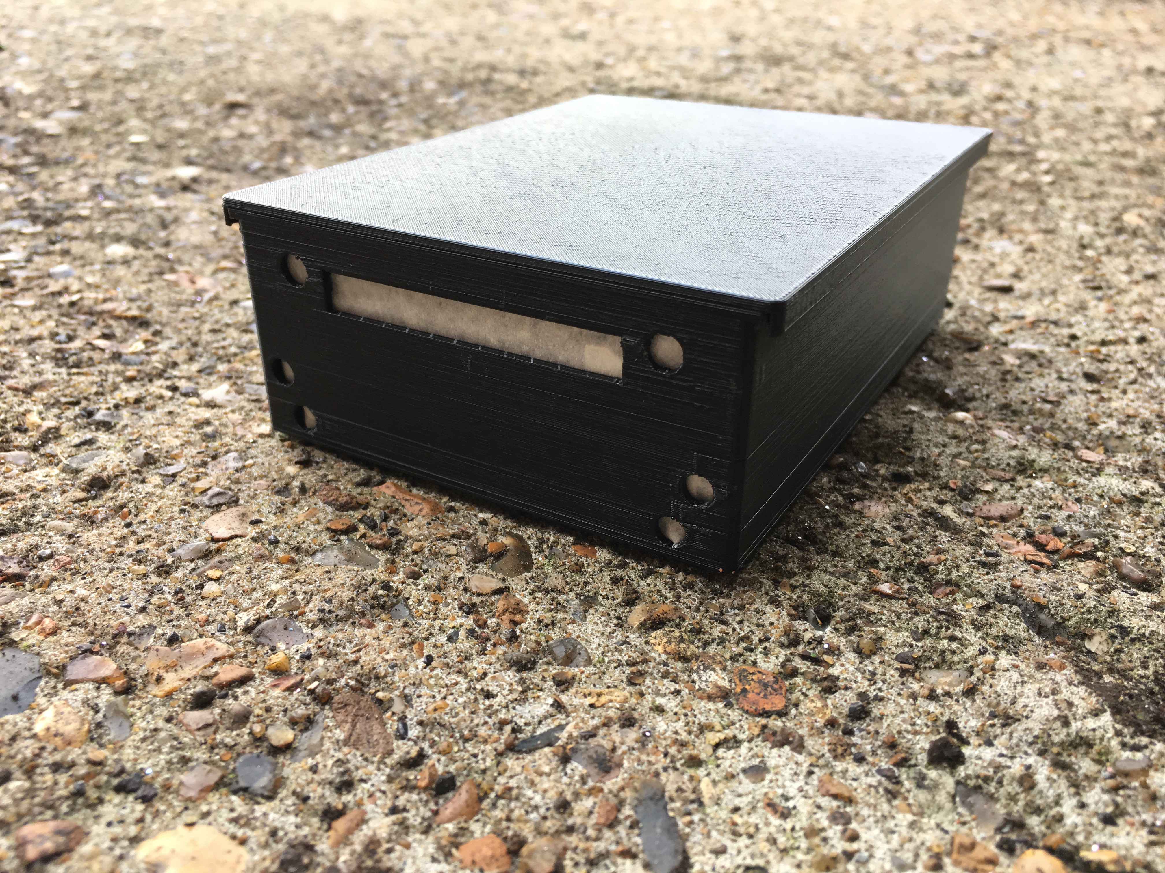
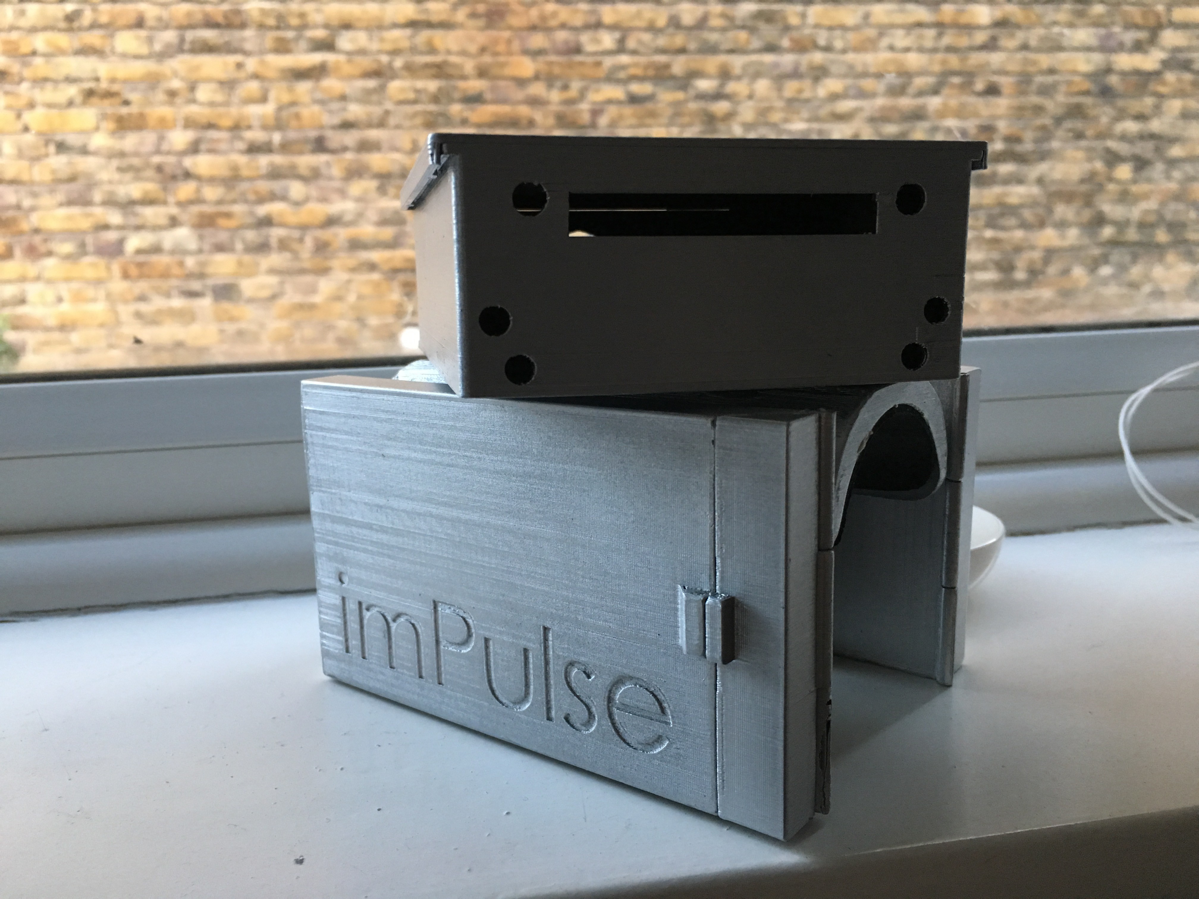
UPDATE - 18/10/18
And here they are! I also glued a rubber sheet and added the M3 inserts to the eBox mounting bracket. Hinges and magnets were also added to the power bank housing. It looks nice, isn't it?!
Q&A Section
Is it possible to make a reduced-size circuit?
I am sure it is possible. What I am doing is very simple and I am planning to design a proper PCB that I am sure that will be more compact.
How does the power bank charge and discharge sequence work?
This a good one because it affects the whole system design. The charging state has priority over the discharging, so the system was designed having this little but crucial aspect in mind.
Discussions
Become a Hackaday.io Member
Create an account to leave a comment. Already have an account? Log In.