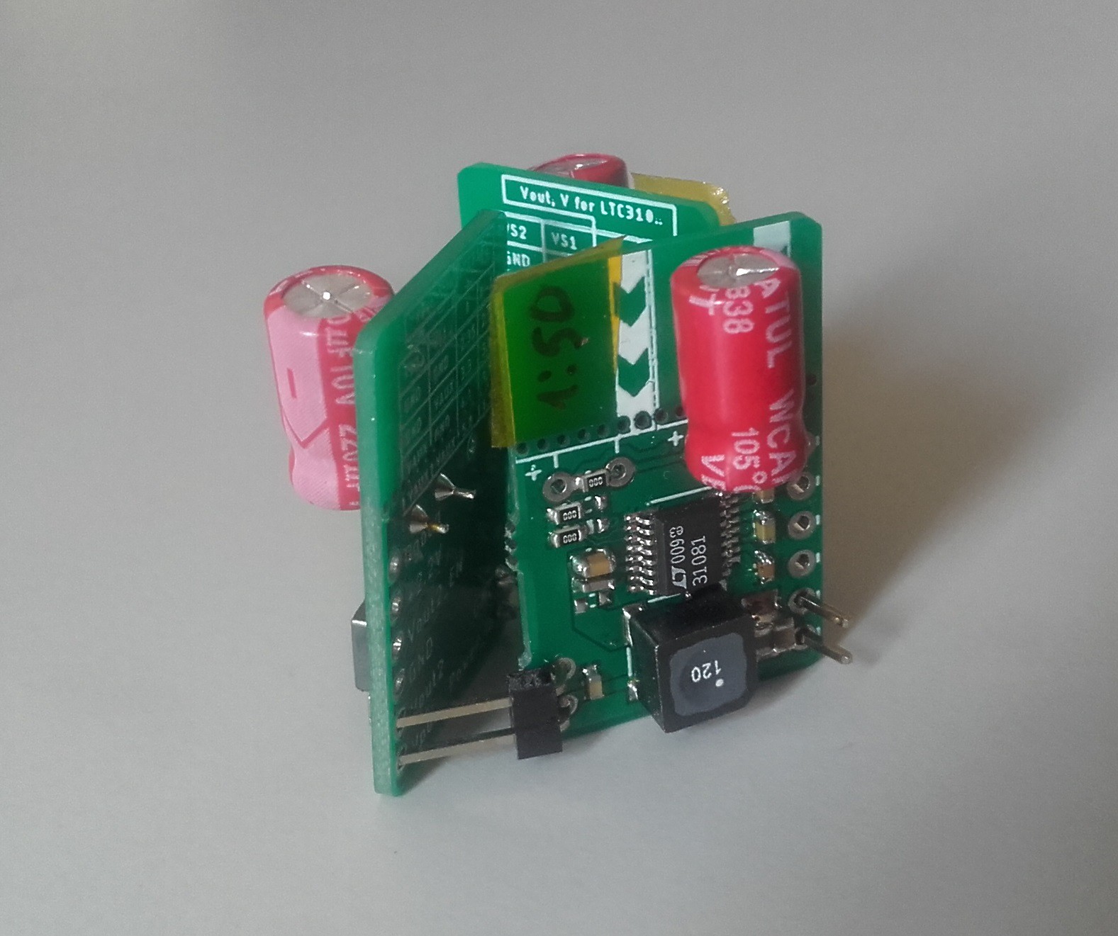
Last week, I've been searching for the problem in energy harvesting IC. The schematics and layout looked very simple, however, I managed to make mistake here =).
I suspected that issue is in component values, because I tried to use the closest nominal values I had at the moment (i.e. instead of 4.7uF - 10uF, instead of 330pF - 470pF, etc,).
But, after I resoldered the most critical components , the situation was the same: the circuit just didn't want to start!!! - Pointing with oscilloscope into different nodes of circuit didn't help to understand "WHY?!".
Then I googled pictures for the evaluation kits and devBoards with this LTC chip, to see - what's difference there (that's the bonus side of designing circuits that already exist! ) . And at some moment, I noticed there, that inductor is placed with the 1-st pad in opposite direction. Later, when I rotated it 180° on all my 3 boards, everything started working like a charm! - I'll fix this in documentation.
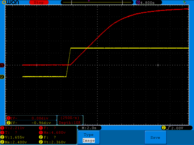
Here is the screenshot from oscilloscope, which made me happy :)

Yellow line is voltage on Vout node, red line - voltage on Vstore node - everything just like in datasheet! I used ordinary power supply as power input, where I set 100mV voltage and current limit around 10mA)
The conlcusions are:
1) The reason of mistake was: I didn't pay attention, that coil is asymmetric, and one side have just a few turns, but the other - hundreds!! So, If I want it to increase voltage, then I need place side with few turns to low-voltage source :)
2) It's much simpler to solder 0603 component on 0805 footprint, than vice versa. Therefore if space allows, and I have not only 0603 but also lots of 0805 in my stock, for first prototypes better to use 0805 footprints.
 and, actually, you can charge one of these boards from another, which charges from another one :D
 Jurist
Discussions
Become a Hackaday.io Member
Create an account to leave a comment. Already have an account? Log In.