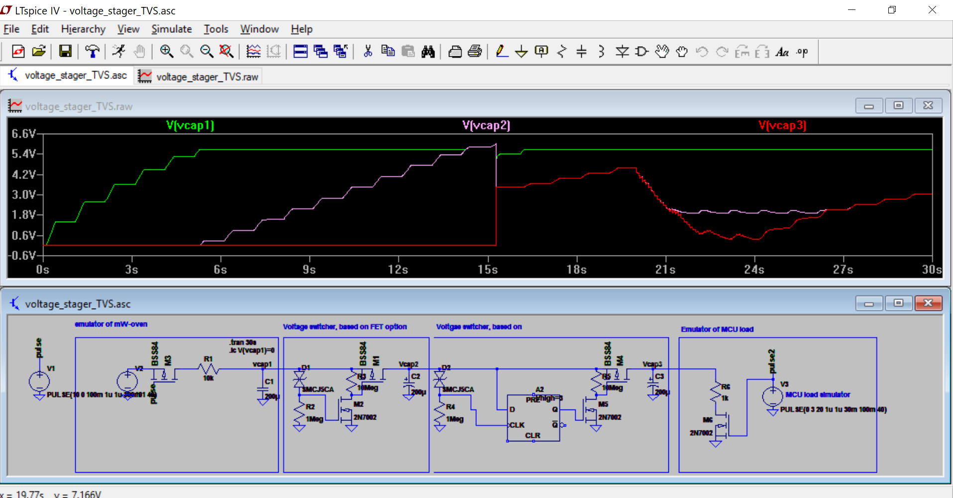
Oh, I remembered, that I promise to post the schematics, I designed for Voltage switching: when capacitor is charged up to some level, P-Fet, connected to next stage (i.e. MCU, or other capacitor), turns on, thus powering next stage, or multiple such stages (remember idea with many caps and their quantity depending on accumulated energy?).
I didn't use this circuit in last design, because this switching is already provided by power management chip ;)
I've made simulations in LT-Spice, (the best tool ever!!!) - see "File" section of project for LT-Spice files. Looks like idea should work =) and power consumption should be low enough too.

In one design as voltage reference for "turn on voltage" I've used tvs diode in other - LEDs in forward connection (which gives lower voltages than TVS, and lower leakage currents); different color LEDs provides different "turn on voltages" :)
I tried to recreate mW-oven as pulsed current source, so it charges capacitor periodically (when food is in "correct position" in oven)
switching stages are implemented two options: one, connecting diode-resistor circuit directly to N-FET, other - through 74AUP1G79 or similar D-type flip-flop.
As seen from simulation, behaviour of circuits is different: in first scenario, second stage charges smoothly, until reaches voltage of first stage.
In second scenario, when D-type flip-flop turns on P-FET, all energy "excess" from cap before P-FET transfers to cap after P-FET, until their voltage is equal.
I also implemented one more stage, that simulates LOAD, to see, how everything operates, if it discharges all caps.
I haven't implemented this design in PCBA ;
Therefore, at the moment there is only mWessenger_v2.0 PCB (which I reviewed in previous post), ordered, and I'm waiting for it now.
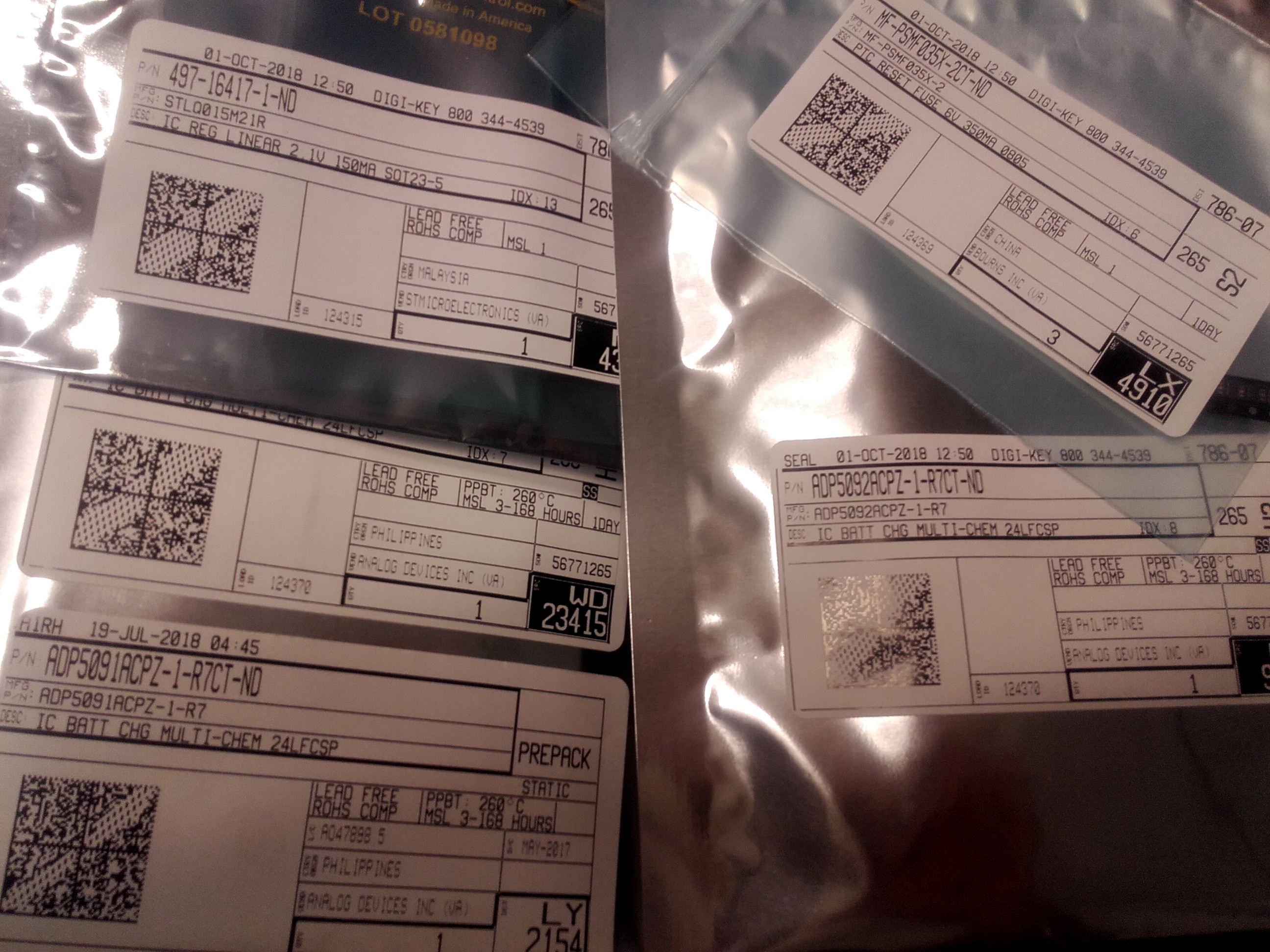
Btw., part of components, ordered from Digikey already arrived :)

 Jurist
Discussions
Become a Hackaday.io Member
Create an account to leave a comment. Already have an account? Log In.