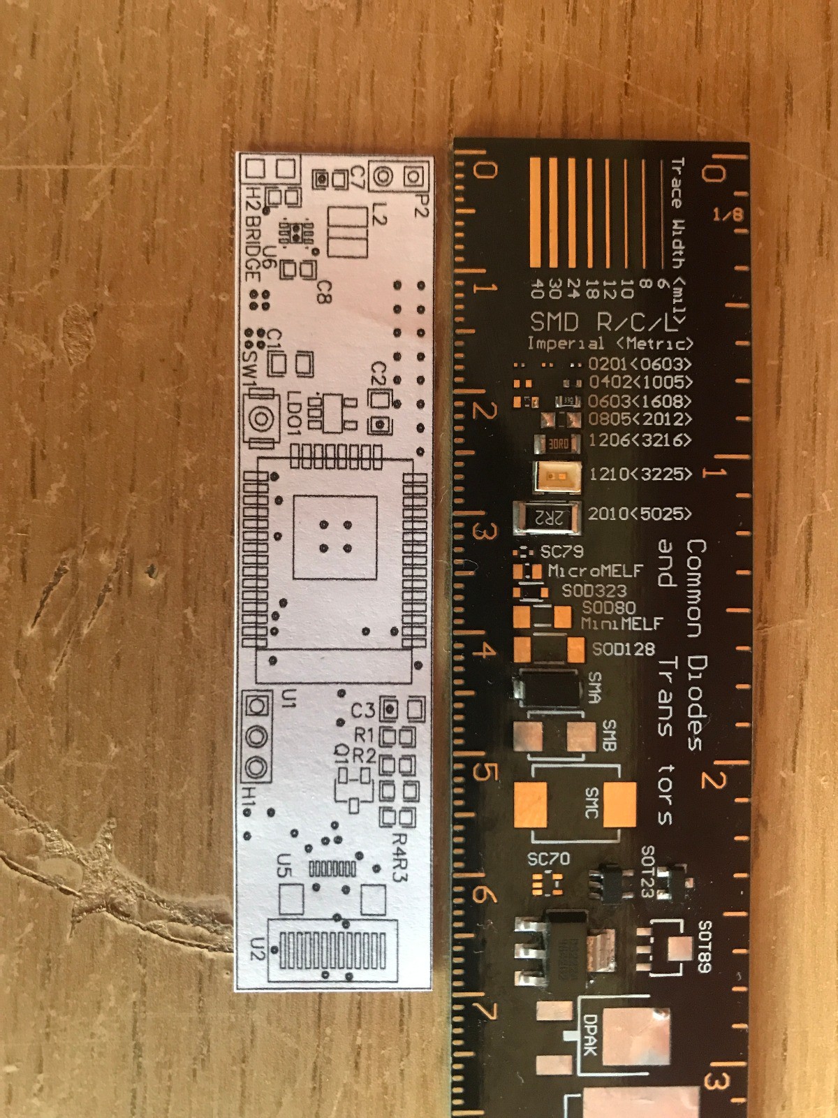
This is a PCB design I've created that lets me integrate the new ESP32 module I bought with the other components like TFT IPS display, battery and power switch. There is a 3v to 5v boost circuit on the PCB and I have designed the PCB to let me use the ENABLE pin on the boost IC with a switch (to turn the chip on and off with the switch) or to keep the ENABLE high all the time with a solder bridge or 0 ohm resistor.
I did this just as an experiment because I was wondering how other complex devices can be controlled by one switch like a laptop which has so many IC's that need to turn on at different times. So this was my opportunity to experiment with it, if it doesn't work I can just pull the EN pin high with resistor.
I also have an LDO regulator there because I'm not sure if the boost circuit will even work, If it doesn't I can cut the traces and solder the battery straight to the LDO inputs and job done. Also most importantly the ESP32 needs 3.3v to operate with a suggested minimum output current of 500mA which this chip certainly does have.
On the far right, you can see pads for an FFC/FPC connector and another array of pads to the right of it. This is so that the PCB can let me use both kinds of my display. There is one type with an 8 pin 0.5mm pitch FFC and another which is meant to be soldered to a board with 13 pins at a pitch of 0.7mm I think (I couldn't find any connectors with this pitch either). The bank of capacitors, resistors and transistor between U1 and U5 are those components that you see on the back of every display module out there. I just looked at the datasheet for the display and drew a schematic of the display module using continuity mode on my multimeter in order to see how exactly it was all connected.
Next up, I have a FPC connector to DIP adapter board coming, this will let me test my new displays without the blue driver board and see if they work with my ESP32. Then I can move on to altering the code I found online to start displaying messages on the screen.
Discussions
Become a Hackaday.io Member
Create an account to leave a comment. Already have an account? Log In.