One idea for making the pentagonal faces into switches was to use IR sensors like in my previous large musical geodesic dome. In that project, the IR sensors are above the diffusers. For the Bucky Glow, I wanted the IR sensors to be underneath the plexiglass. The idea was that enough IR radiation would pass through the plexiglass to be detected.
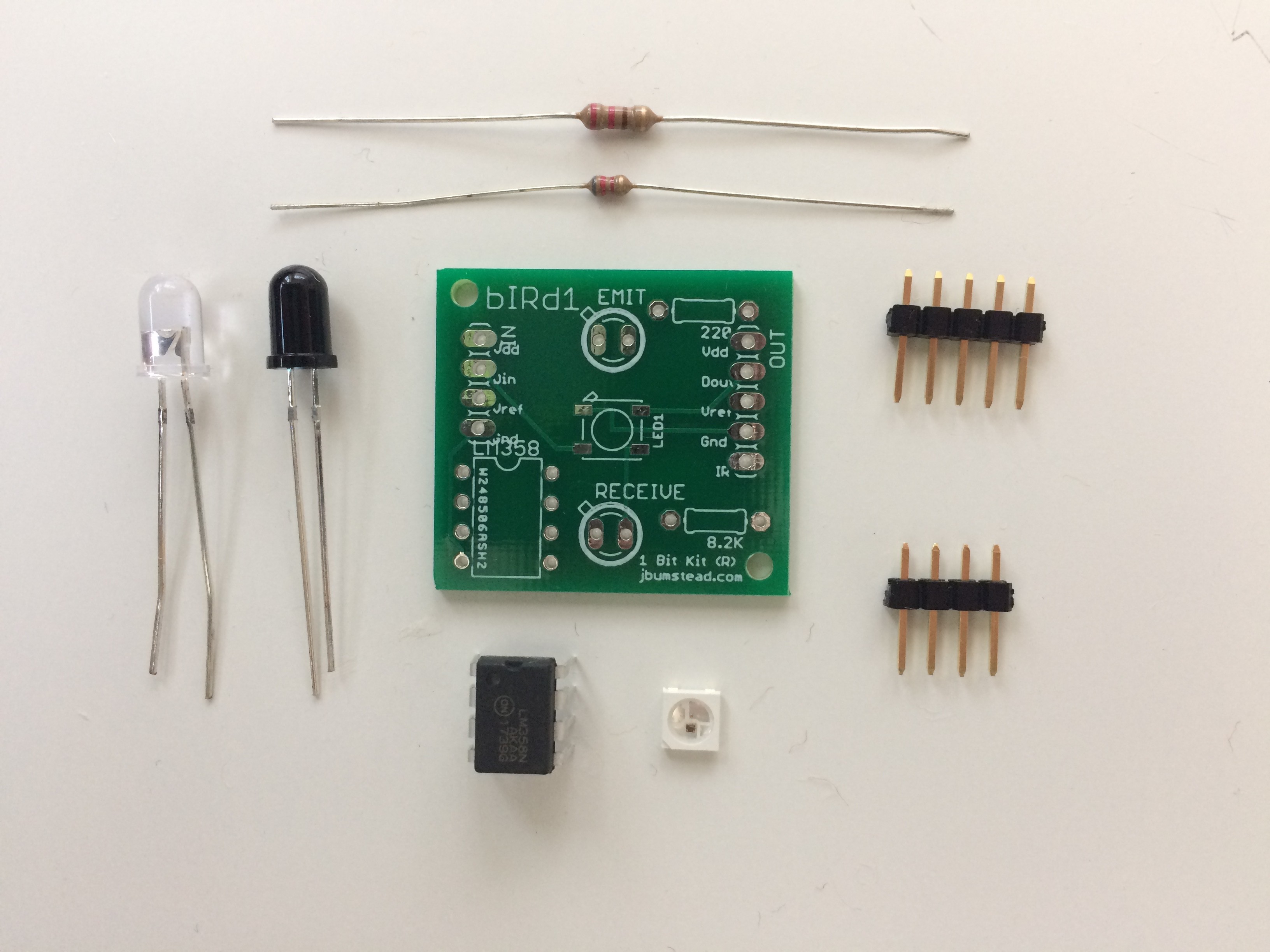
I designed the IR sensor circuit to be incorporated in the same PCB as the LED for the face. The output of the receiver portion of the IR sensor goes to a comparator with a reference voltage provided by an input pin on the board. I wanted to eliminate the need to "tune" each IR sensor like the dome, so every board would have the same reference voltage (which could be adjusted depending on the situation.
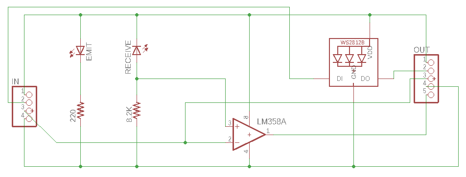
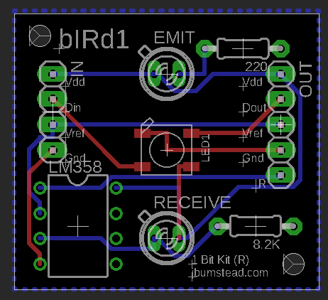
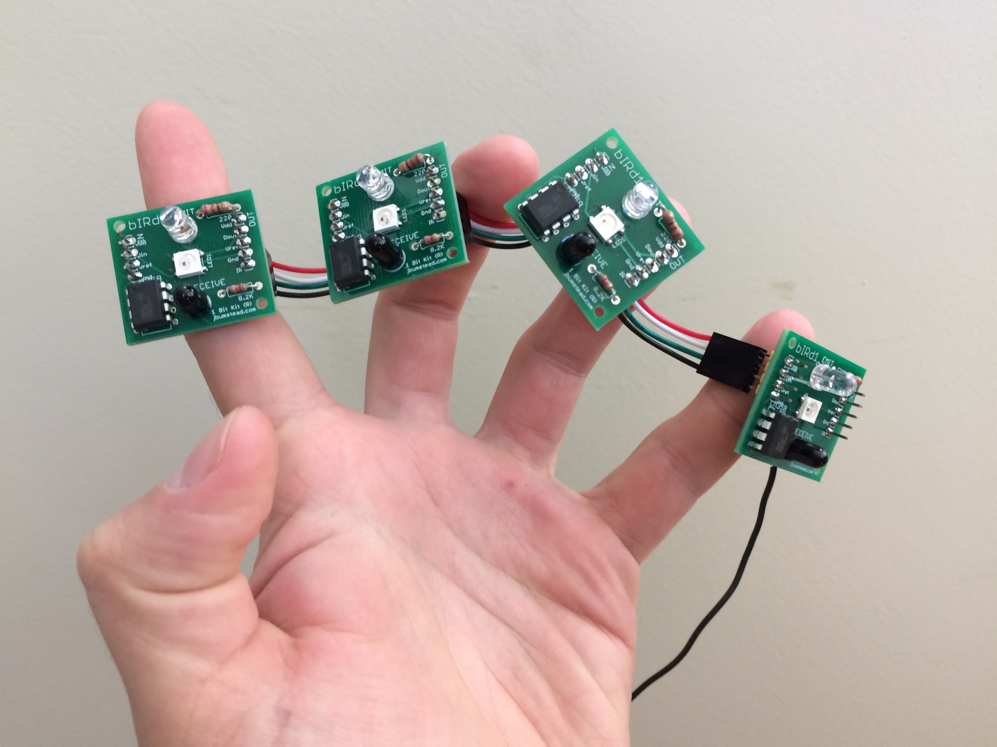
The output IR-LED board could then be connected to the next IR-LED in the circuit. Feeling confident in the design, I had the PCBs manufactured and shipped. I soldered several boards and started testing. The LED strip worked just fine, but then I started having issues with the IR sensors.
First, the outputs were heavily dependent on the lighting conditions. If there was too much IR radiation in the room, then the sensors would start to go off. I could handle this in software, but decided I wanted a better hardware solution.
Second, the white plexiglass attenuated the IR radiation too much.
Third, the signal measured was highly dependent on the angle of the IR emitter and receiver. Because I wanted all the boards to have the same reference voltage for the comparator, varying signals that resulted from slight differences in how the IR emitter and receiver were mounted posed a major problem.
There were probably ways to make this PCB work in software and by paying close attention to soldering orientation, but in the end they just weren't reliable enough.
Version 1: Reference voltage on board
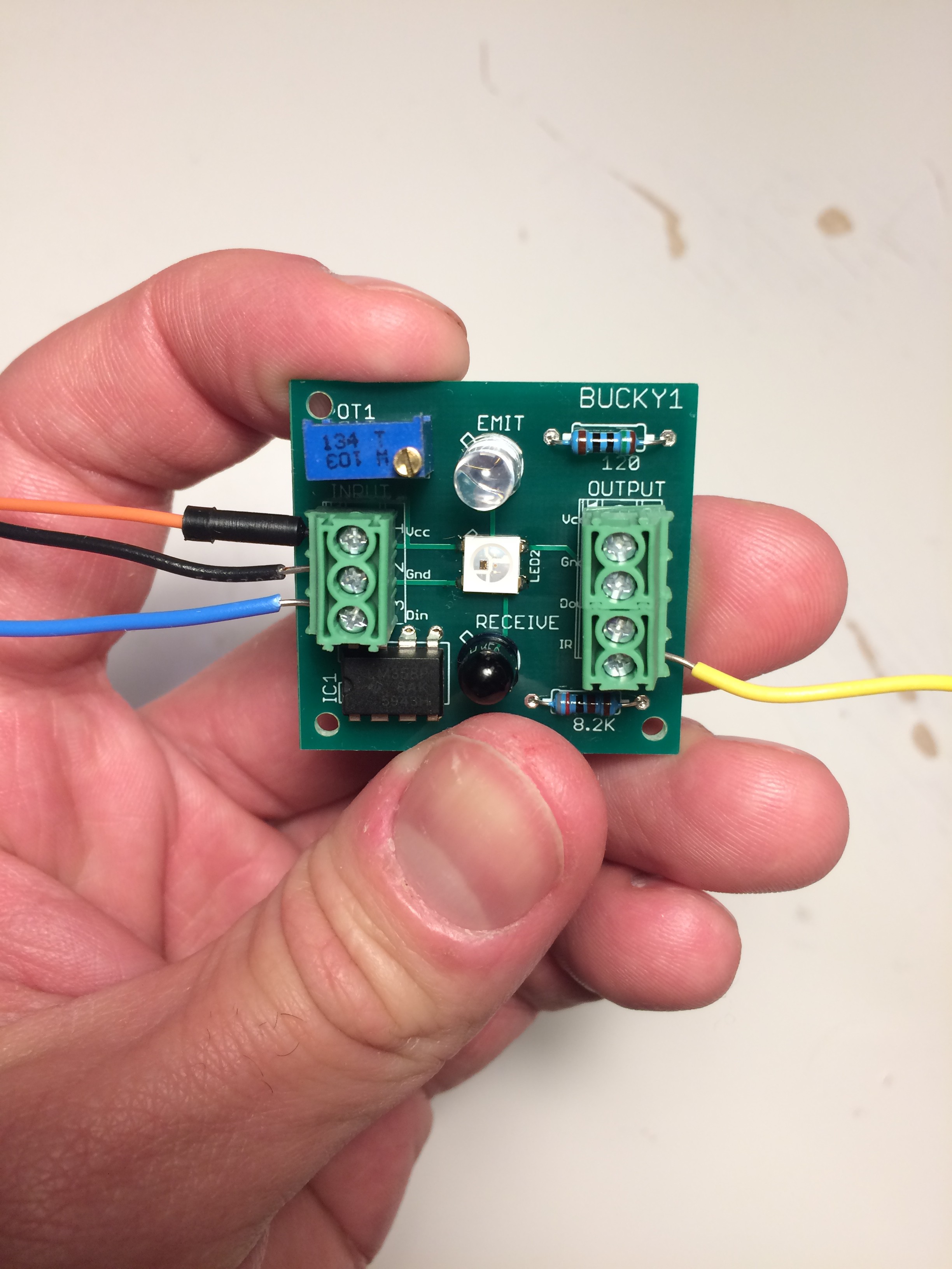
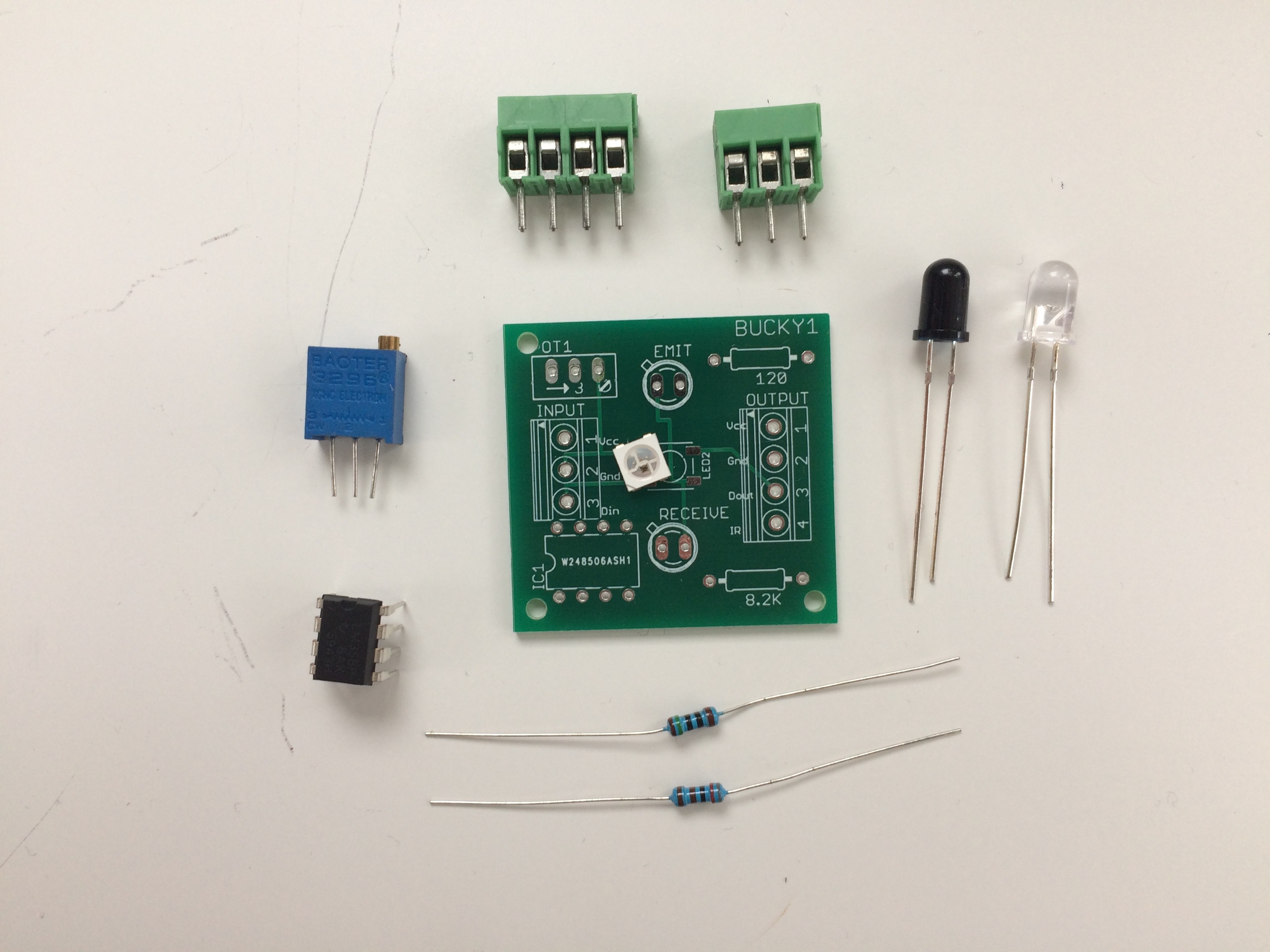
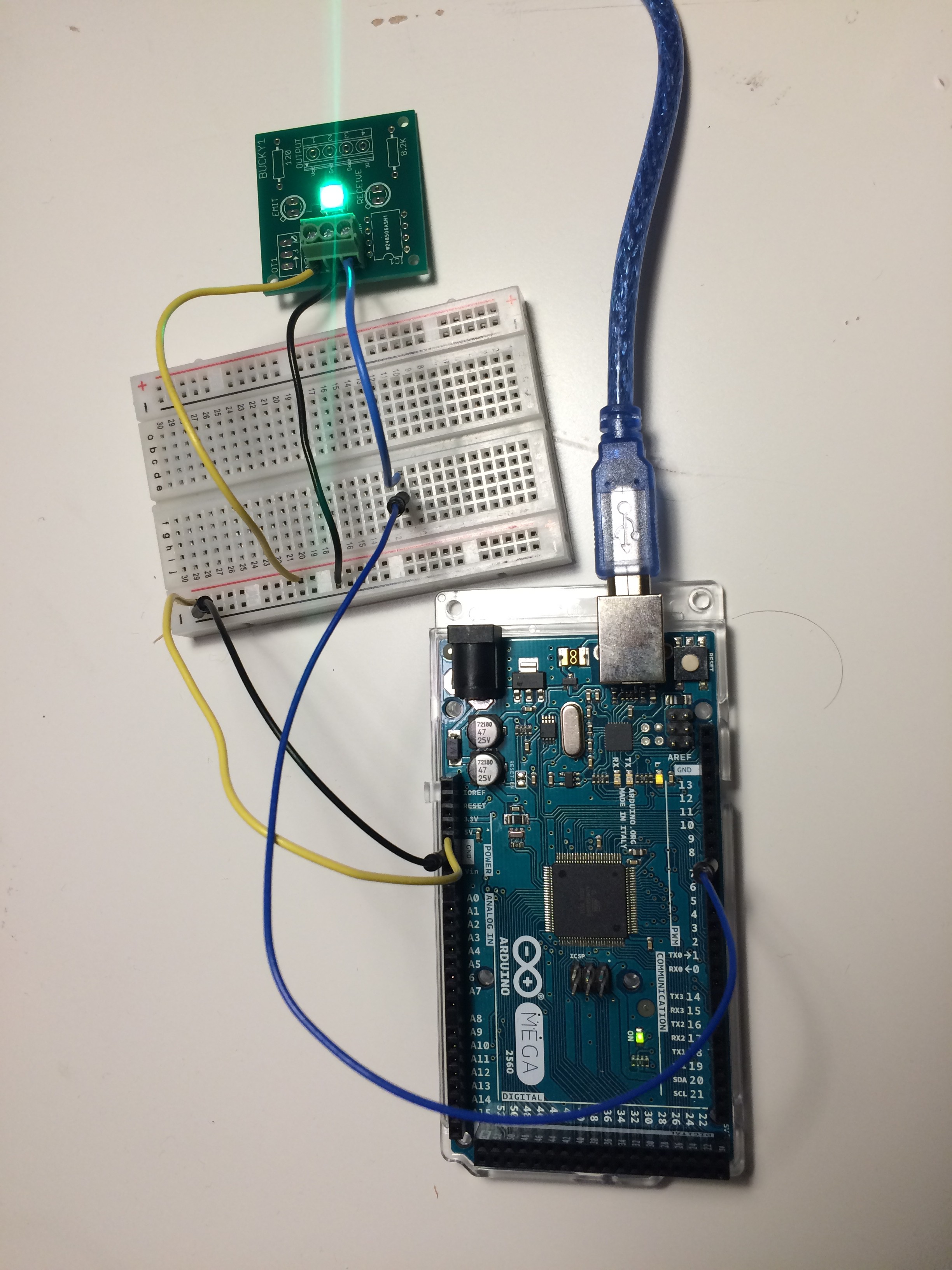
Version 2: Reference voltage off board
 Jonathan Bumstead
Discussions
Become a Hackaday.io Member
Create an account to leave a comment. Already have an account? Log In.