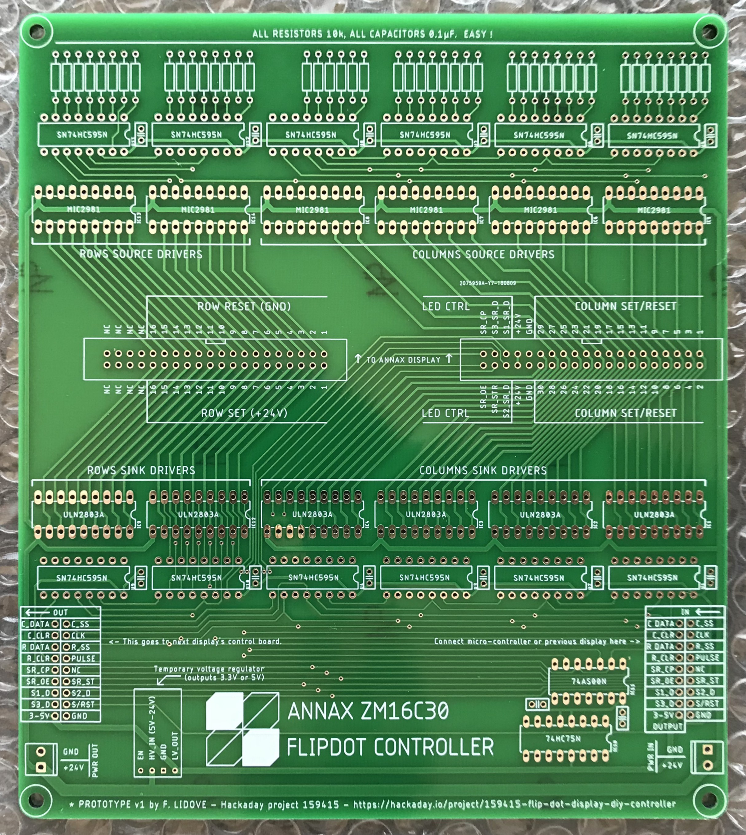
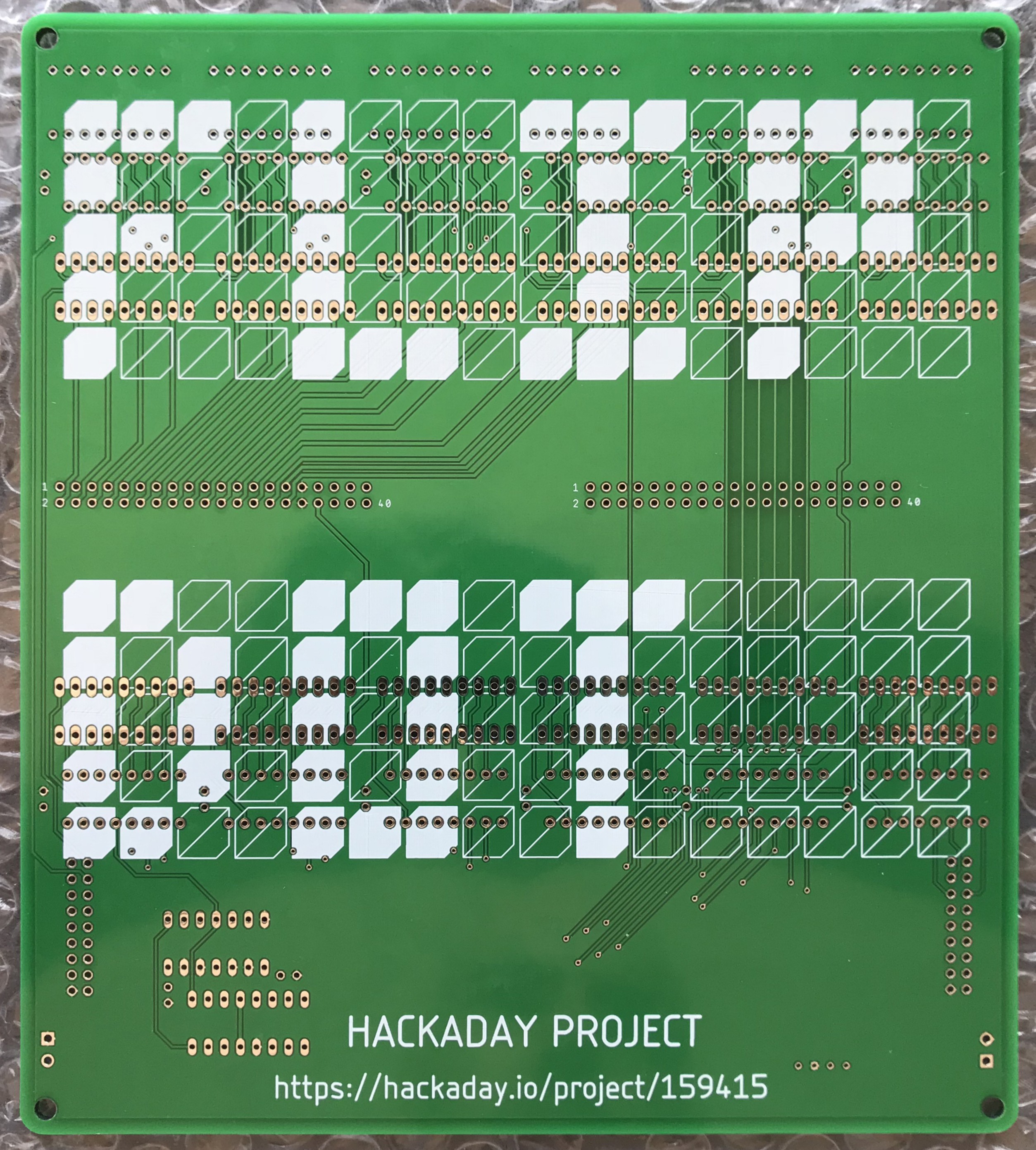
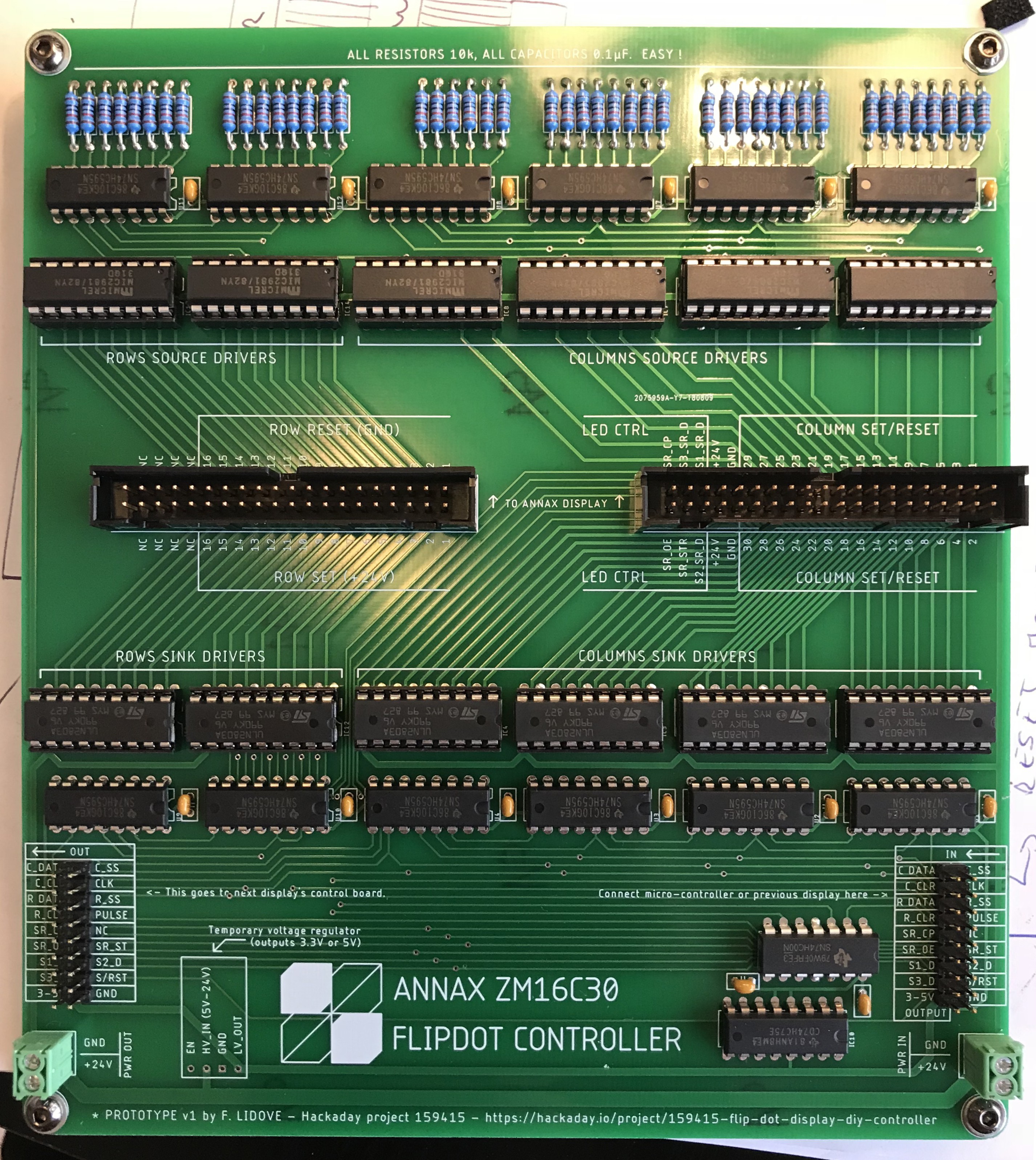
Got the parts yesterday and started putting it all together. Here is the board as I received it from JLCPCB, and the final result with all the components soldered (not my best soldering job but got much better at it towards the end).


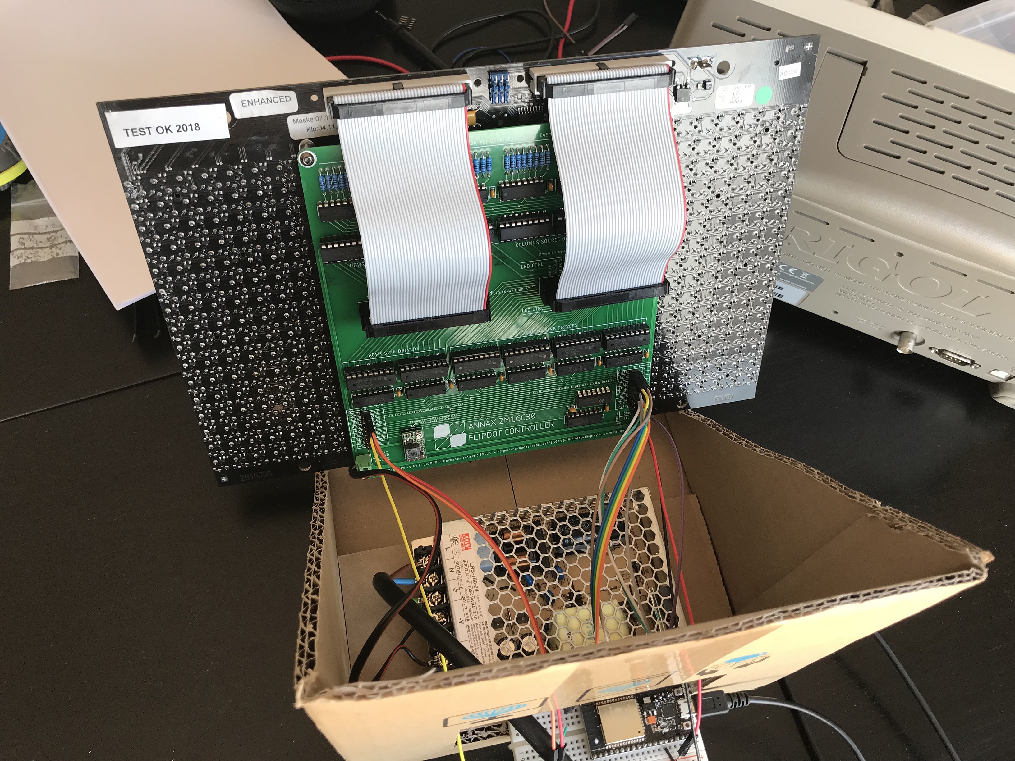
The board fits nicely on the back of the display with 10mm spacers. The 40pins connectors are aligned with the ones from the display and all seems to fit as I was hoping. You can see the power supply here as well in the temporary cardboard support.

I could only find a couple of small mistakes so far :
- The pads holes for the voltage regulator module are too small, so instead of using standard PIN headers I had to solder stripped wires
- The silkscreen should read ROW SET (+24) above connector 1 and ROW RESET (GND) below it, instead of the opposite
I’ll make sure I’ll correct those before posting the board and schematic on GitHub.
Off to some coding and hopefully dots will flip soon !
 Frederic L
Discussions
Become a Hackaday.io Member
Create an account to leave a comment. Already have an account? Log In.