Z80 Single-board computer (with AVR controller)
Another Z80 single-board computer.
Another Z80 single-board computer.
To make the experience fit your profile, pick a username and tell us what interests you.
We found and based on your interests.
Wait_State_Generator-8Mhz-0ws_Live.pdfProgrammable wait-state generator, logic analyzer capture, 8MHz/0ws, M1 = 240nSAdobe Portable Document Format - 12.59 kB - 10/20/2016 at 21:37 |
|
|
Wait_State_Generator-8Mhz-7ws_Live.pdfProgrammable wait-state generator, logic analyzer capture, 8MHz/7ws, M1 = 1120nSAdobe Portable Document Format - 13.29 kB - 10/20/2016 at 21:37 |
|
|
Wait_State_Generator.jedProgrammable wait-state generator, JEDEC filejed - 4.42 kB - 10/20/2016 at 21:36 |
|
|
WSGEN-1V00.siProgrammable wait-state generator, logic equations- 2.67 kB - 10/20/2016 at 22:07 |
|
|
WSGen-1v00.PLDProgrammable wait-state generator, simulation input- 3.16 kB - 10/20/2016 at 22:12 |
|
|
Create an account to leave a comment. Already have an account? Log In.
Friday, October 7, 2016
My design criteria was to use off-the-shelf IC's, attempting to stay as close to the original 1980's technology. A few DIP IC's mixed with a few SMT parts to trim the PCB area down as small as possible, thereby cutting PCB fabrication costs.
The original design was a basic Z80 SBC with 32KB of ROM mapped in at 0x0000 to 0x00FF (for boot code) and 0xE000 to 0xFFFF (utils, monitor ROM and BASIC) with 56KB of RAM mapped from ox0100 to 0xDFFF. I was planning to put a simple CP/M compatible bootloader in the first 256 of ROM, which would be able to boot CP/M from an SD card. The SD card interface would be emulated with an AVR. Since I have a few, I was planning to use an 82C51A UART and use an 82C55 as a simple parallel I/O device. To simplify and reduce "glue-logic" gate count, I would dust off my CUPL skills from a decade or so ago and make use of some LATTICE GAL20V8Z SPLD's I still had from when I worked in the industry as a disti-FAE. This initial design was designated V1.00.
As I got to thinking more about how I wanted to merge the project with an AVR, I started to think that it would be much easier, more efficient and provide some luxuries by using the AVR as a system controller, which would have access to the Z80's Adress, Data and Control lines. I could then do away with the ROM and pre-load the RAM with a bootloader, Monitor, BASIC, etc. at power-up or user-initiated RESET. Using one of the AVR's 8-bit timers, I could use the OCxA (or OCxB) output to directly drive the Z80's clock and peripherals through a buffer. Maximum speed would be the AVR's system clock divided by two. I would have control of the Z80 reset line as well. Hence the V1.10 design was born.
The AVR of my choice is the AT90USB1286 with it's built-in USB controller in hardware and many I/O ports, most being 8-bits wide, which would work well for the byte-wide address and data buses. With the AT90-USB1286, to talk with the system controller, I could use a simple Virtual COM port, which is directly supported by the Linux and Windows OS's. That would also save me from having to use a serial-to-USB adapter (FTDI, CP2102 or the like) with the 82C51A as I could feed the 82C51A's TX and RX pins to the AVR's TXD and RXD pins and use the AVR as a serial pass-through device. I could use one of the AVR's 16-bit timers to generate the baud rate clock for the 82C51A as well. Using Timer 1 of the AT90USB1286, I could divide the AVR's clock down to 122Hz. With 16-bit resolution, I can effectively support ANY desired "industry standard" baud rate. At 115.2K, 57.6K, 38.4K, 19.2K and 9600 baud, the calculated error is 0.08%, which is well within the acceptable tolerance. That's pretty darn good! With the AVR as a pass-through, I could monitor the serial input stream for a certain control character to signal it to take control of the serial I/O and allow me to talk to the AVR system controller for "house-keeping" functions and utilities, like single-stepping, code upload and download, setting the Z80 clock speed, etc. A low-cost AT90USB1286 development board would be nice to work with and I already have a few of PJRC's TEENSY 2.0++ boards, which come in a 40+ pin quasi-DIP "package", so that's the plan. On the TEENSY 2.0++ board, port F of the AT90USB1286 is fully accessible, which allows me access to the JTAG interface for hardware debugging of my AVR code when I get to that part of the design.
Since I was planning to use an AVR to emulate an SD card as a "disk drive", it seemed that I might as well try to also emulate the 82C51A or as on the RC2014 project, an MC6850 UART, then I could do away with another larg 28-pin 600 mil DIP IC and the baud rate generator circuit. If I emulate the MC6850 UART, then I can use some of the RC2014 code unmodified as that project makes use of the MC6850 UART. If I wanted to, I could emulate the Z80-SIO device as well, which would make more of the Z80 code out there on the net" usable with little modification. Among some of my goals, was to keep the PCB size small to save on fabrication costs. Thus, using the AVR as a UART, SDmem interface and to provide the Z80 clock seemed to be the correct path to follow as it will eliminate at least 3 existing IC's and some passive components as well.
Although I currently see no need to use them, in the V1.10 design, I have left the ADC0 through ADC3 pins (PF0 to PF3) available in case I decide that I need to monitor an analog voltage for some reason. The AVR's TXD and RXD, INT0 and INT1 pins (PD0 to PD3) are also left unconnected thus far. I wanted to leave the INT0 and INT1 pins available in case I need to awake the AVR from SLEEP mode or just respond to a "chip select" for the DISK and UART emulation using the "UART" and "DISK" chip selects.
As for the Z80 system clock, the OC2A output of the AVR provides the Z80 clock. Timer 2 is an 8-bit timer. If the code is set up such that the AVR clock is the clock source to the timer and "mode 2" (CTC mode) is selected, the OC2A pin can be programmed to toggle with an OCR2A match. Thus, the OC2A output will toggle at a rate dependent of the the AVR clock source. If OCR2A is set to "0", there is a divide-by-2 clock for the Z80. The TEENSY 2.00++ clock is 16MHz, which means the fastest my Z80 could run would be 8MHz but setting OCR2A to "1" would drop that to 4MHz. The output frequency would be AVR_CLK / ((OCR2A + 1) * 2). The minimum Z80 clock could be 16MHz/((255+1)*2) or 31.250KHz. As one might imagine, the Z80 clock could even be set to something "odd", say 3.2MHz, 2.666MHz, 1.454MHz, etc. The Z80 clock could be changed on-the-fly, even used to suspend the Z80 in a "standby mode" by forcing the Z80 clock pin low. I plan to implement "single-stepping", which is why running the Z80 at a low frequency of sub-100KHz would be useful as it would give the AVR time to monitor and toggle the appropriate Z80 control pins.
As stated earlier, I have the intention to use the AVR to "download" a "monitor" or CP/M bootloader into the RAM starting at address 0x0000. Since the AVR controls the Z80 RESET pin, the Z80 can be held in a RESET state until the memory dump is complete, then the RESET pin released so the Z80 can continue to execute code from 0x000.
Next up, getting the SPLD to function as an I/O decoder.
Become a member to follow this project and never miss any updates
By using our website and services, you expressly agree to the placement of our performance, functionality, and advertising cookies. Learn More

 Plasmode

 eprive
 Tomeu Capó
Saturday, October 8, 2016
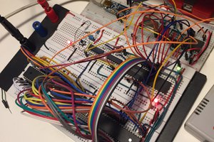
Working on the SPLD to use as an I/O decoder. I have GAL20V8Z's available and the free WinCUPL from ATMEL. I needed five chip selects; UART, PIO, DISK, RAM1 and RAM2. I would like to implement a wait-state generator in case I need to use it at the higher Z80 clock speeds. My first stab at it was a simple I/O decoder splitting the ROM up to access at 0x0000 to 0x00FF and 0xE000 to 0xFFFF, RAM1 at 0x0100 to 0x7FFF and RAM2 at 0x8000 to 0xDEFF. I needed to use A[15..8] along with the MREQ and IORQ lines. Oops! WinCUPL failed because I needed too many product terms. I then tried the same with a GAL22V10 and it fit, so I ordered some but they are 3 to 4 weeks away coming from China. Next I committed myself to nix the ROM, which allowed me to use just A[15..12], thereby simplifying my design to fit into the GAL20V8Z's I have. I really wanted to test my code in a live Z80 environment so I wired up a solderless bread-board with a simple ATmega328P, a Z80 with all data lines held low (to execute NOP's) and the GAL20V8Z. The AVR conrols the RESET and CLOCK lines so I wrote a quick program to initialize them and drive the Z80. The photo of the solderless bread-board used for testing this phase of the design is attached.
Note on the GAL20V8Z; it has a nive power-saving feature wherein it looks at all the input pins. If all of them do not change state for a certain time period, the part goes into a low-power standby mode util it sees activity again. Since I am using it as an I/O decoder, I don't see that it will ever get to switch into power-saving mode.
I had some problems getting the GAL20V8Z to function properly. The UART select kept toggling with the MREQ line. Wierd since the simulation showed all test vectors with correct results! After many hours of re-coding CUPL and re-burning GAL20V8Z's, I started to get the impression that it was the programmer because even the simplest boolean equations burned in the SPLD did not function correctly. Since the programmer would let me select GAL20V8, GAL20V8A ,GAL20V8B, GAL20V8C and GAL20V8D parts, tried the GAL20V8D device and it started to work, I was using the GAL20V8 setting, which turned out to be the culprit. Odd since all five parts have the same number of bits in their fuse map.
After getting the I/O decoding to work, I set out to design in the wait-state generator since I had a few output pins left on the GAL20V8Z. I used the 74xx74 D-flip-flop reference right out of the Z80 data sheet. The simulation worked correctly, hi-z until it drove the Z80 WAIT pin low. In reality, I could not get it to work as the WAIT pin never went low. Grounding the OE pin (13) on the GAL20V8Z allowed me to see the states of the internal "wait 1" and "wait 2" signals from the registers and I found the problem, which was corrected. So after several hours diddling with the wait-state generator, I had it working at the 8MHz Z80 clock speed. Time to try lower clock speeds. After switching gears to 4MHz, I could see that the Z80 was held in a perpetual WAIT cycle. Switching back to 8MHz and the problem cleared. Hmm... This should not be happening as the internal flip-flops are clocked by the Z80 clock and driven by the MREQ line. A few more hours of diddling and I decided that if I was going to need the wait-states, they would be at the 8MHz clock speed so I added a WS-EN (wait-state enable) pin to be driven by the AVR. If the AVR is generating 8MHz for the Z80 then it will enable the wait-states, if not, then it disables the wait-state generator and now the Z80 functions fine at the lower clock speeds, all the way down to 31.250KHz. After musing over the RAM IC data sheets for the IDT and CYPRESS 32Kx8 static RAMS I have, the cycle time is 150ns between sequential reads. It is likely that I will never need wait-states for the RAM ... but I may need them to interface with the AVR UART and DISK emulation.
Next up; Interfacing with the 74HC299.
If anyone has any input on why the wait-state generator only functions when the clock speed is 8MHz, I have posted the CUPL code below and I would appreciate some feedback and/or tips.
[code]
Name Z80_IOdecode-1V10;
Partno Z80C;
Revision 01;
Date 9/20/2016;
Designer Quest, Johnny;
Company KSV;
Assembly Z80 Computer;
Location U4;
Device g20v8a;
/*******************************************************
* ___________
* | Z80_IOdec |
* sys_clk x---|1 24|---x Vcc
* !mreq x---|2 23|---x !rst
* !iorq x---|3 22|---x UART_sel
* ws_en x---|4 21|---x PIO_sel
* x---|5 20|---x !DSK_sel
* x---|6 19|---x wait1
* x---|7 18|---x wait2
* a12 x---|8 17|---x !WAIT
* a13 x---|9 16|---x !RAM1_sel
* a14 x---|10 15|---x !RAM2_sel
* a15 x---|11 14|---x !m1
* GND x---|12 13|---x !oe
* |____________|
*/
/*******************************************************/
/* This device generates chip select signals for two */
/* 32Kx8 static RAMs. */
/* It also drives the system WAIT line to insert a */
/* wait-state of at least one cpu clock for all memory */
/* accesses. 1 wait-state is internally generated by */
/* the Z80 for I/O accesses */
/*******************************************************/
/** Inputs **/
PIN 1 = sys_clk; /* System Clock */
PIN 2 = mreq; /* Z80 MREQ (active low) */
PIN 3 = iorq; /* Z80 IORQ (active low) */
PIN 4 = ws_en; /* Wait-state enable (active high) */
PIN [8..11] = [a12..a15]; /* upper 4 address bits */
PIN 13 = !oe; /* Output Enable (active low) */
PIN 14 = m1; /* Z80 M1 (active low) */
PIN 23 = rst; /* System reset (active low) */
/** Outputs **/
PIN 22 = UART_sel; /* 82C51A UART (active high) */
PIN 21 = PIO_sel; /* 82C55A PIO (active high) */
PIN 20 = DSK_sel; /* SDmemory interface (active low) */
PIN 19 = wait1; /* Internal Use (combinatorial logic out only) */
PIN 18 = wait2; /* Internal Use (combinatorial logic out only) */
PIN 17 = WAIT; /* insert 1 WAIT-STATE (active low) */
PIN 16 = RAM1_sel; /* 32Kx8 RAM (active low) */
PIN 15 = RAM2_sel; /* 32Kx8 RAM (active low) */
/** Declarations and Intermediate Variable Definitions **/
FIELD address = [a15..12]; /* upper 4 addresses */
uart_eqn = !iorq & !m1 & address:[0000]; /*******************************/
pio_eqn = !iorq & !m1 & address:[1000]; /* */
dsk_eqn = !iorq & !m1 & address:[2000]; /* I/O Address */
/* Ranges */
ram1_eqn = !mreq & !m1 & address:[0XXX..7XXX]; /* */
ram2_eqn = !mreq & !m1 & address:[8XXX..FXXX]; /*******************************/
/** Logic Equations **/
/* UART/PIO select (active high) */
UART_sel = uart_eqn; /* high for addresses 0000h-0FFFh */
PIO_sel = pio_eqn; /* high for addresses 1000h-1FFFh */
/* DSK select (active low) */
DSK_sel = !dsk_eqn; /* low for addresses 2000h-2FFFh */
/* RAM select (active low) */
RAM1_sel = !ram1_eqn; /* low for RAM addresses 0100h-7FFFh */
RAM2_sel = !ram2_eqn; /* low for RAM addresses 8000h-DFFFh */
/* wait state generator */
wait1.d = (!mreq # !iorq); /* Synchronous Wait-state */
wait2.d = wait1; /* wait1 delayed */
WAIT.oe = ws_en & wait1 & !wait2; /* Turn Buffer ON */
WAIT = !(ws_en & wait1 & !wait2); /* End Wait */
[/code]