 Lucy Fauth
This isn't my first phased array that I built. Actually, my seconds version is working perfectly fine and has all features I wanted to have. Still, I don't feel like that's what people should read about when considering building their own arrays. And here is why.
First, some specs about V2. I won't go too much into detail, anyway feel free to ask questions if you want to know something particular.
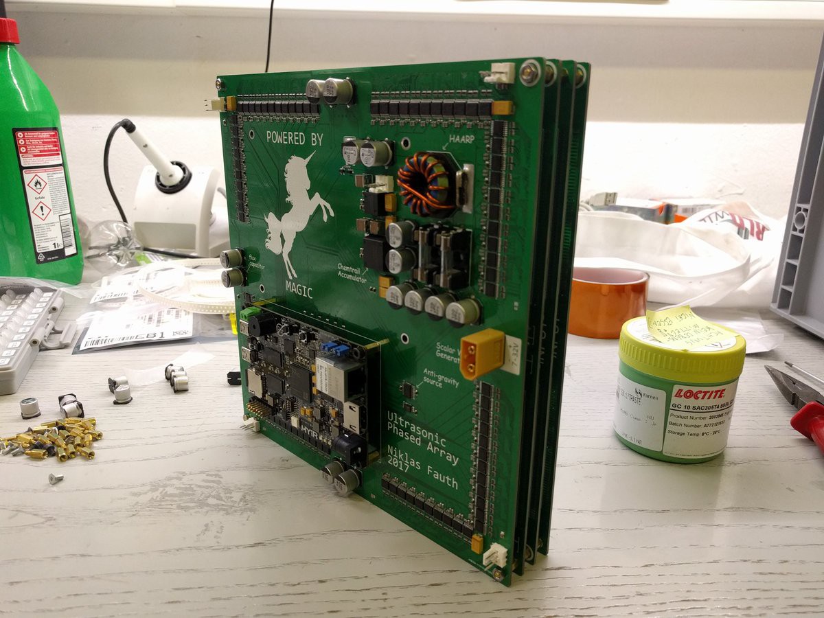
- Xilinx Zynq as the main processor. Linux debian running on the ARM core, all the logic to generate the waveforms run on the FPGA.
- The array is represented as a 19x19 framebuffer (fb0) in linux, each pixel for one transmitter. Red color for phase shift, blue color for power.
- There is also an ALSA sink available that can be used for audio modulation.
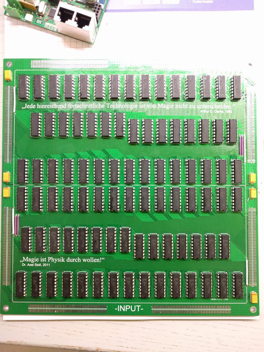
- 8 bit shift registers on each of the 91 IOs of the FPGA to get the required 722 waveforms (per transmitter one for signal, and one for enable (to do PWM)).
- L293 as cheap power drivers, one fullbridge for each transmitter.
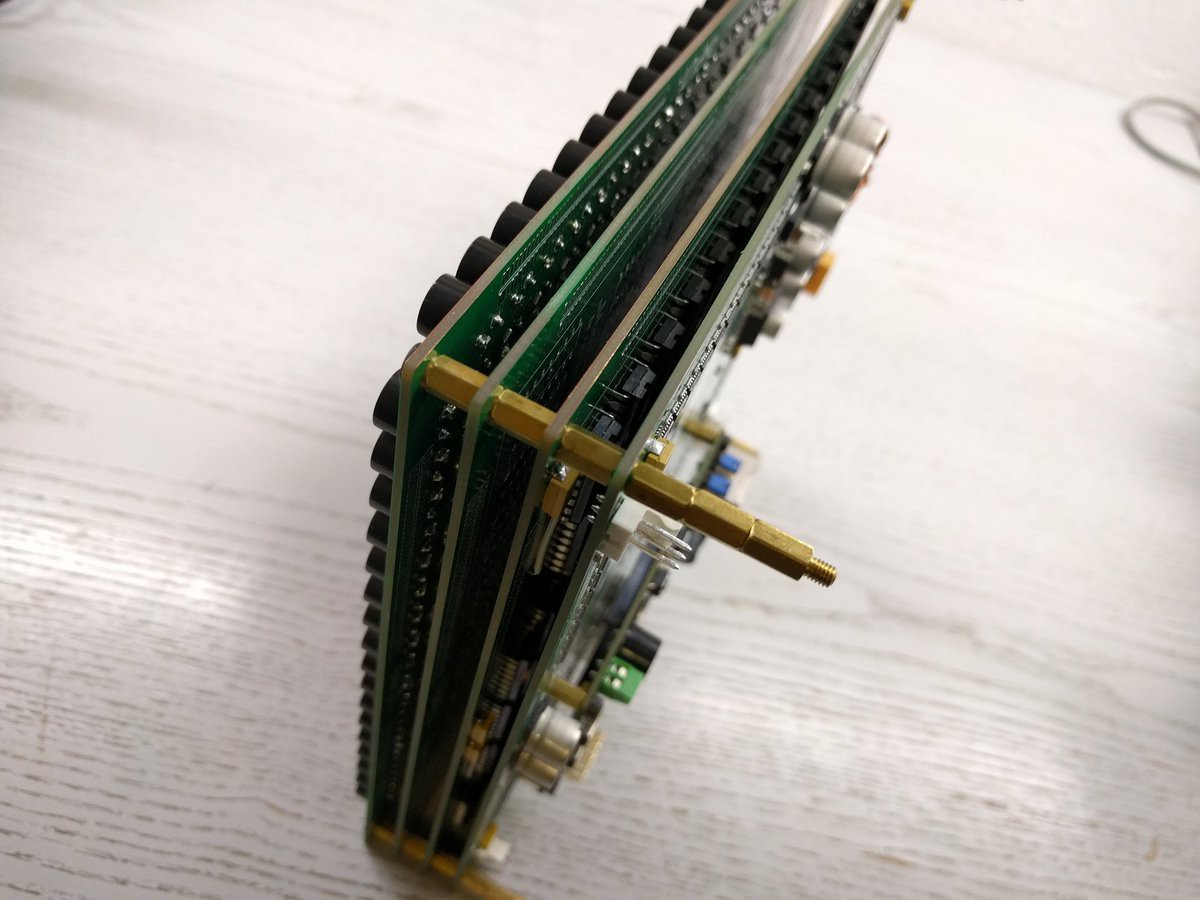
- 4 sandwiched pcbs, bottom is FPGA & shift registers & power, than 2x driver boards + the transducers.
Some pictures:
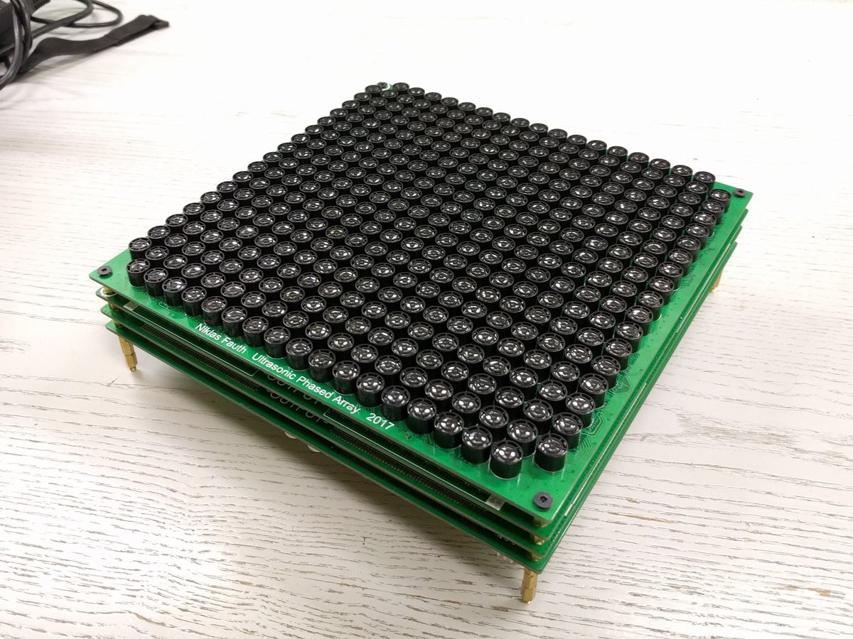
When I started this project, I didn't know anything about phased arrays. There were some papers about the theory of operation and the maths behind it, but they all used simulations for their proposals. I tried contacting the guys who made this initial levitation youtube video, without success. I knew that I would need to control the transducers individually, and I knew that I need a lot of them. However, I didn't knew if there is a minimum amount of transducers that is necessary, and more important, with what resolution I need to control the phase. And because I wanted to be sure that it works in the end, both of these parameters turned out the be complete overkill in my design. I built a highly sophisticated, completely overengineered array with 19x19 transducers, 10 bit (1024 steps) phase resolution and 8 bit (256 steps) power resolution for each transducer, that, because if this, caused me a lot of trouble. 19x19 because that's the amount of transducers I was able to stick to my fpga, and 10 bit resolution because I was worried a lot that I would need super high resolution for everything to work smooth.
Well, turned out 5 bit (32 steps) are totally fine, and 19x19 transmitters is complete overkill. Not only did this false assumption wasted a lot of time and money, it also caused lots of troubles that are directly connected to this overkill: Thermal problems, high error rate because of the insane amount of components etc.
Especially, I wanted version 3 to be more rebuild friendly. To achieve that, I wanted to change few things:
- Single driver pcb, completely self-contained
- 16x16 transducers, which is still more than enough
- better cooling of the power drivers
- replaceable driver-to-array connectors (especially the female connector parts)
- cheap design (< 200$ total)
Anyway, not everything was bad with array version 2. Things I really enjoyed about it:
- single 12V power supply
- Linux running on the phased array. It is soooo good to have a ssh access to debug stuff.
- Ethernet with TCP/IP for communication. Super fast and easy to use on both sides of the cable.
Discussions
Become a Hackaday.io Member
Create an account to leave a comment. Already have an account? Log In.