One of the most important parts of an ultrasonic phased array are the amplifiers that drive the individual ultrasonic transmitters. It needs to drive around 2nF of capacitance per channel at 40kHz, which is about 50mW in average at 36Vpp. Unfortunately, this is also the hardest part to find when designing an array.
A good idea to start searching for are MOSFET gate drivers. These are designed for exactly that application, charging the gate capacitance of a MOSFET at high frequency, so these work perfectly fine for our application. However, these have to problems: First, they are rather expensive. I wasn't able to find one for < 20ct. This doesn't sound like much, however second, these usually come in single-channel configuration. This means you would need 256 individual ICs for a 16x16 array, or 50€ worth of gatedrivers.
That is also the reason why I used the l293 for V2. These have two full-bridge drivers per chip, so you can drive 4 transducers with a single IC. Also, they are dirt cheap when you buy them on AliExpress (4-5ct / pcs). Unfortunately, they are only available in DIP package, which is a pain to solder. Seriously, try soldering 90 DIP-16 packages.... hfgl.
The other thing is driving all these transmitters. You need at least 256 IOs, and neither a fpga nor an ARM processor has that many GPIOs (at least not in the user-friendly, low-cost range). So you will probably need some shift registers. Cheap candidates are 74HC595, and they indeed work perfectly fine. However you would also require 256 / 8 = 32 of these...
Long story short, everything sucks with standard components. This is why I was very happy when I had a look at Microchips HV driver ICs: That was when I learned about the HV583 IC. This isn't a particularly new IC, it was originally introduced by Supertex in 2003. However, back then it was only available as a bare die, so you would have to bond it to your pcb to use it. This was until Microchip bought Supertex and repackaged the HV583 design in a 169-TFBGA package. I know it's BGA and it is not the easiest to solder, but at least now it's possible to use it at all.
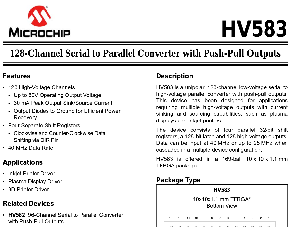
Here is a sneak at the datasheet which might help to understand why I'm so excited about this part:

This single IC combines the shift registers + the amplifiers for 128 transducers in a single package. It takes two of them to power the whole array. Also, they are super cheap: 12€ for single quantities at Mouser, 7€ at 500pcs via Microchip direct. In fact, you can even sample four of these from Microchip for free.
The only disadvantage about these ICs is that they are rather slow, and the shift registers are connected as 4x 32bit. This gives us a maximum phase resolution of (40MHz / 32 bit) / 40kHz = 31.25, so roughly 5 bit.
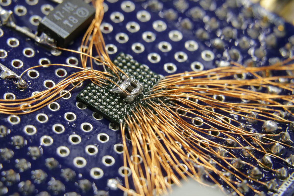
The other thing is the rather low output power of 30mA. This means that the internal RdsOn of the output driver stage is rather high, from my measurements in the range of 50-70 Ohms. This creates lots of internal losses that heat up the chip. To test if it is generally possible to use the HV583, I made a small breakout board of the IC in deadbug style:

I attached 32 transmitters to some output channels and generated a static 40kHz signal. Everything seemed to work fine, until after 30s the outputs switched off. The thermal camera showed a peak temperature of 120°C. So the chip went into over temperature disable. However this was without any cooling, neither from the pcb it was not soldered to nor from any forced airflow. So, let's hope when soldered to a proper pcb, cooling works okay.
If that should fail, I still have a backup plan: The HV582. It is basically identically to the HV583, however it has only 92 output with 75mA driving capacity. This means that I would need 3 instead of 2 chips, but that's still way better and cheaper than any of the discrete solutions mentioned earlier.
 Lucy Fauth
Discussions
Become a Hackaday.io Member
Create an account to leave a comment. Already have an account? Log In.