 Chris Graham
Things accomplished since previous log entry:
- Assembled the photo-sensing parts and the air pressure tube into a mouthpiece shell milled from black FDA compliant acetal copolymer by FirstCut (part of Protomold). The mouthpiece I had was slightly out of date and did not have a place for an air flow tube but this will be added in the next prototype. The photo sensors consist of an LED infrared emitter/phototransistor pair for the lower lip and the same for the oral cavity. I potted the parts into place and sealed the mouthpiece by filling it with silicone. Eventually medical grade epoxy will be used but I don't have it yet so I used silicone aquarium sealant which is safe and works fine although it's messy to work with and hardens slower. The silicone's high viscosity makes the job look messy but it's good enough for now.
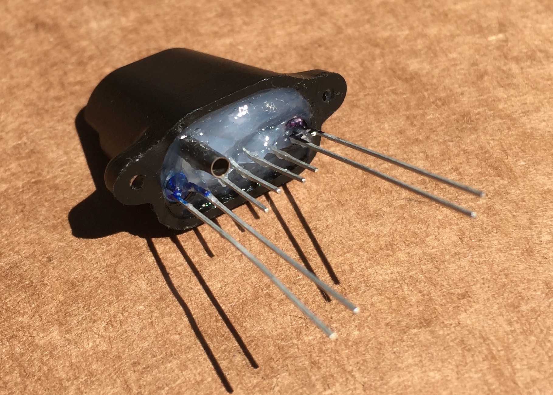
Note that the above picture still does not have the lip light pipes installed.
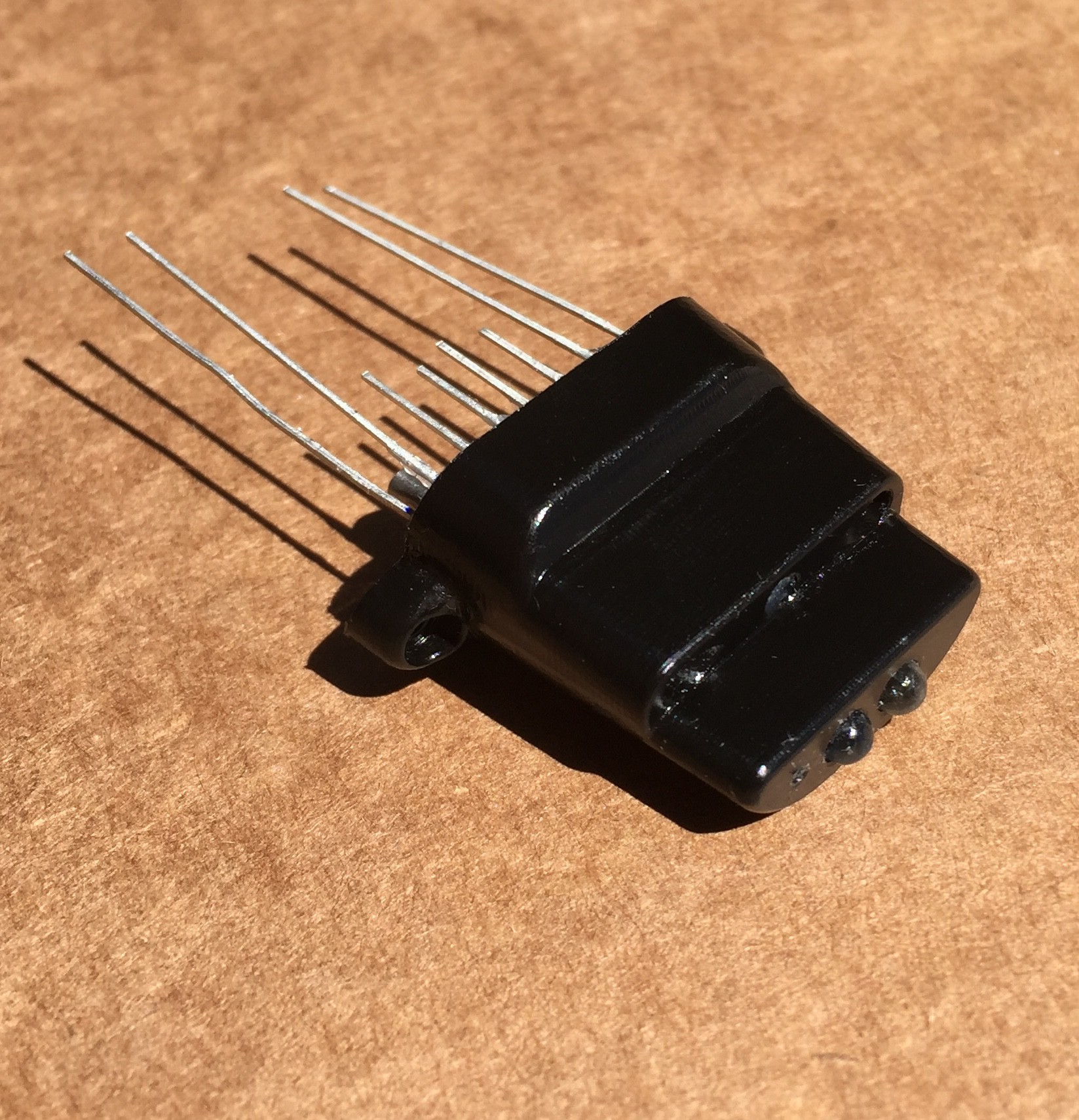
- The leads of the photo-parts need to exit in a straight line with 0.1 inch (2.54mm) separation so they can be plugged into a standard connector.
![]() Forming the leads is tricky to do accurately enough so I designed and 3D printed die for forming the leads:
Forming the leads is tricky to do accurately enough so I designed and 3D printed die for forming the leads: ![]() To use: Place the head of the part in the cavity on the left upper surface of the die, hold the head down firmly, press the leads into the forming surfaces and you have leads with the perfect shape. You can see I made blue and black markings on the parts to distinguish LEDs from Phototransistors as they look exactly the same.
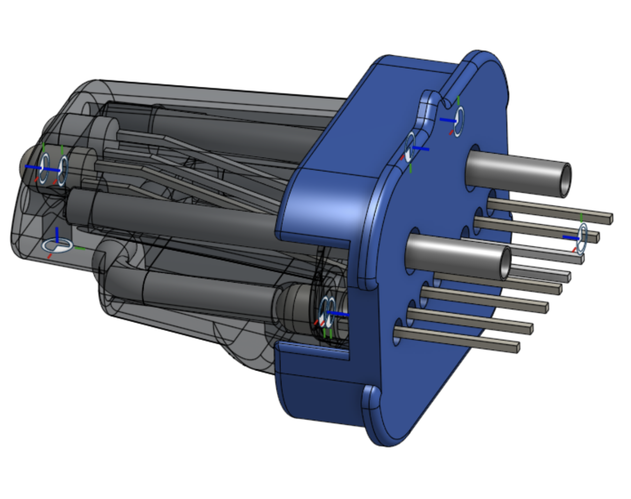
To use: Place the head of the part in the cavity on the left upper surface of the die, hold the head down firmly, press the leads into the forming surfaces and you have leads with the perfect shape. You can see I made blue and black markings on the parts to distinguish LEDs from Phototransistors as they look exactly the same. When potting the parts it's necessary to hold the parts in alignment until the potting compound dries. I designed and 3D printed an alignment jig that can be placed on the back of the mouthpiece and has holes for the leads and tubes. The jig is the blue part in the picture above that also shows the internals of the mouthpiece. This is what it look like in use.
![]() The jig can be removed when the potting compound hardens. For the future I'm going to make a version of the jig with a hole to inject the potting compound through. Also I ordered a tube of this epoxy from Atom Adhesives: https://www.atomadhesives.com/AA-BOND-FDA2-FDA-Grade-Epoxy-Adhesive-Medical-Food
The jig can be removed when the potting compound hardens. For the future I'm going to make a version of the jig with a hole to inject the potting compound through. Also I ordered a tube of this epoxy from Atom Adhesives: https://www.atomadhesives.com/AA-BOND-FDA2-FDA-Grade-Epoxy-Adhesive-Medical-FoodThen I hooked up the mouthpiece to a breadboard for testing. This picture shows just the lip sensor connected to resistors and power from the breadboard.
![]() This was the first time trying this significantly changed design since I last worked on the project five years ago. It was a big moment! And it worked perfectly! Amazingly controllable, Of course all that can be seen now are changing voltages from the sensors based on lower lip/jaw and tongue/throat throat position. However for both sensors it's possible to select, hold and repeatably return to a wide range of positions. When mapped to music controllers this should give a great playing experience.
This was the first time trying this significantly changed design since I last worked on the project five years ago. It was a big moment! And it worked perfectly! Amazingly controllable, Of course all that can be seen now are changing voltages from the sensors based on lower lip/jaw and tongue/throat throat position. However for both sensors it's possible to select, hold and repeatably return to a wide range of positions. When mapped to music controllers this should give a great playing experience.Also, while potting the parts I realized that it would also be possible to at the same time attach a stainless steel electrode in the top of the mouthpiece. This would provide capacitive sensing of upper lip position. I've been looking for a practical way to add upper lip sensing for a long time and this should be perfect! Inexpensive and not much harder to assemble than without it. Basically it could be a strip of stainless steel 1/4" (6.35mm) wide, 20mm long and 0.5 mm thick. There's an available capacitive sensing port on the Teensy. A slot and support for the front of the electrode could be included in the injection mold design. The underside of the electrode would sit on the hardened medical grade epoxy. A slot to align the electrode could be added to the part alignment jig. Here is the hole for the electrode. Extending the hole all the way to the back and adding draft to the edges is what makes injection molding possible.
![]() Some sort of connection would be needed from the electrode to the main PCB. There are several ways this could be done.
Some sort of connection would be needed from the electrode to the main PCB. There are several ways this could be done.
 Forming the leads is tricky to do accurately enough so I designed and 3D printed die for forming the leads:
 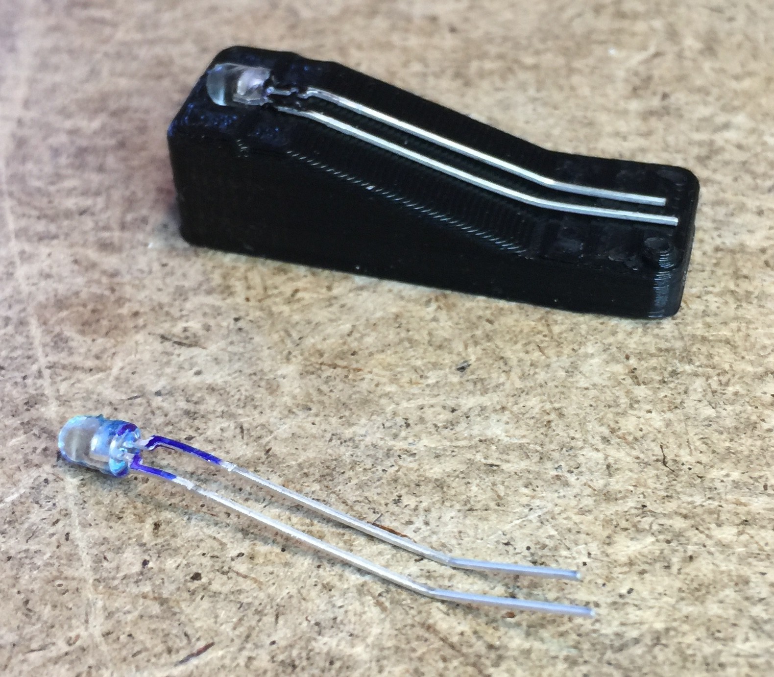 To use: Place the head of the part in the cavity on the left upper surface of the die, hold the head down firmly, press the leads into the forming surfaces and you have leads with the perfect shape. You can see I made blue and black markings on the parts to distinguish LEDs from Phototransistors as they look exactly the same.
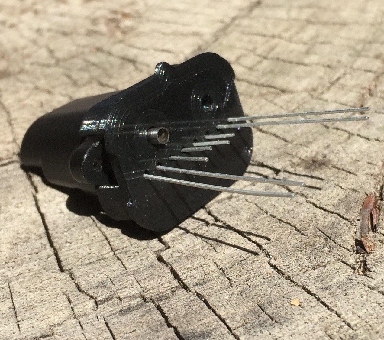 The jig can be removed when the potting compound hardens. For the future I'm going to make a version of the jig with a hole to inject the potting compound through. Also I ordered a tube of this epoxy from Atom Adhesives:
 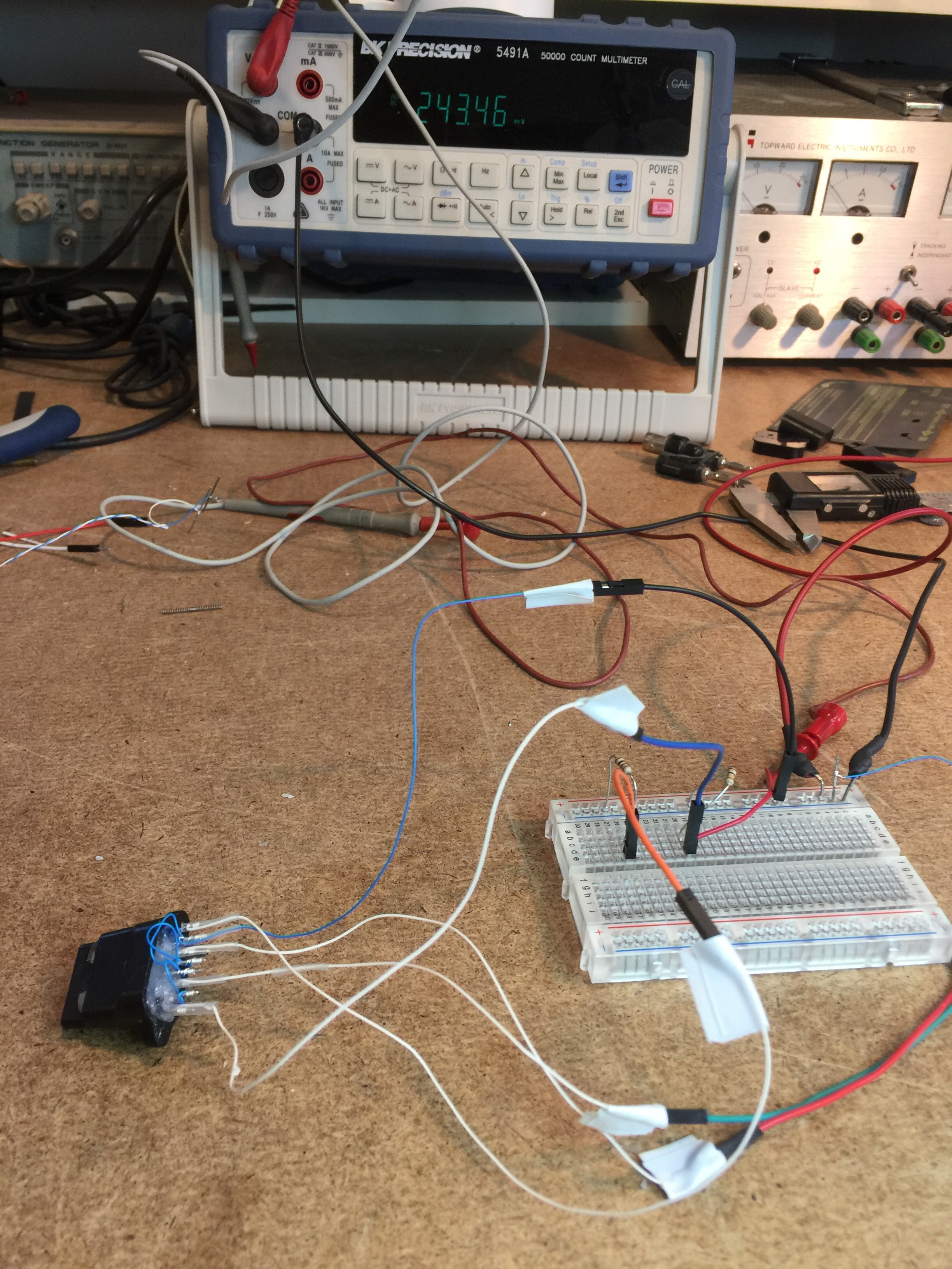 This was the first time trying this significantly changed design since I last worked on the project five years ago. It was a big moment! And it worked perfectly! Amazingly controllable, Of course all that can be seen now are changing voltages from the sensors based on lower lip/jaw and tongue/throat throat position. However for both sensors it's possible to select, hold and repeatably return to a wide range of positions. When mapped to music controllers this should give a great playing experience.
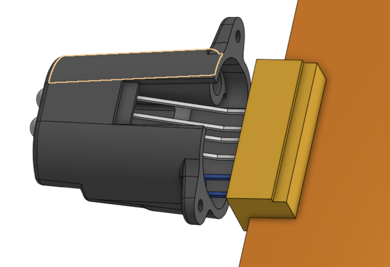 Some sort of connection would be needed from the electrode to the main PCB. There are several ways this could be done.
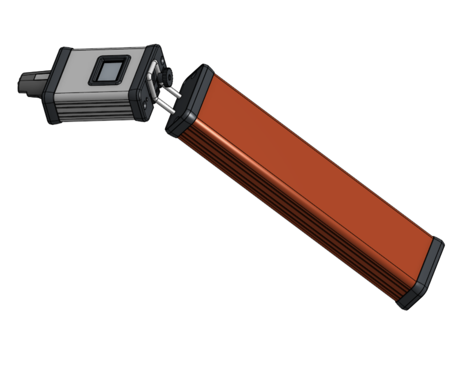
This rendering shows the latest version of the overall concept. You can see the electrode in the top of the mouthpiece and proposed bezel for the display.
![]() I like how it's looking. The mouthpiece is 65mm long which seems about right. This finger unit housing (no keys yet) is what might be used for a woodwind. The total length including mouthpiece is about 300mm or about 1 ft. A brass style instrument could be shorter if desired.
I like how it's looking. The mouthpiece is 65mm long which seems about right. This finger unit housing (no keys yet) is what might be used for a woodwind. The total length including mouthpiece is about 300mm or about 1 ft. A brass style instrument could be shorter if desired. I still haven't received the new PCBs which will get here next week. Then I'll assemble the board, add the mouthpiece and try reading the sensors with the Teensy. I'll post another update after that.
Note that these designs will be publicly available. In fact they probably are now - the 3D model on OnShape.com and the schematic on EasyEDA.com but I'm not suggesting people look at them yet as I'm changing them frequently.
 I like how it's looking. The mouthpiece is 65mm long which seems about right. This finger unit housing (no keys yet) is what might be used for a woodwind. The total length including mouthpiece is about 300mm or about 1 ft. A brass style instrument could be shorter if desired.
Discussions
Become a Hackaday.io Member
Create an account to leave a comment. Already have an account? Log In.