 Matthew James Bellafaire
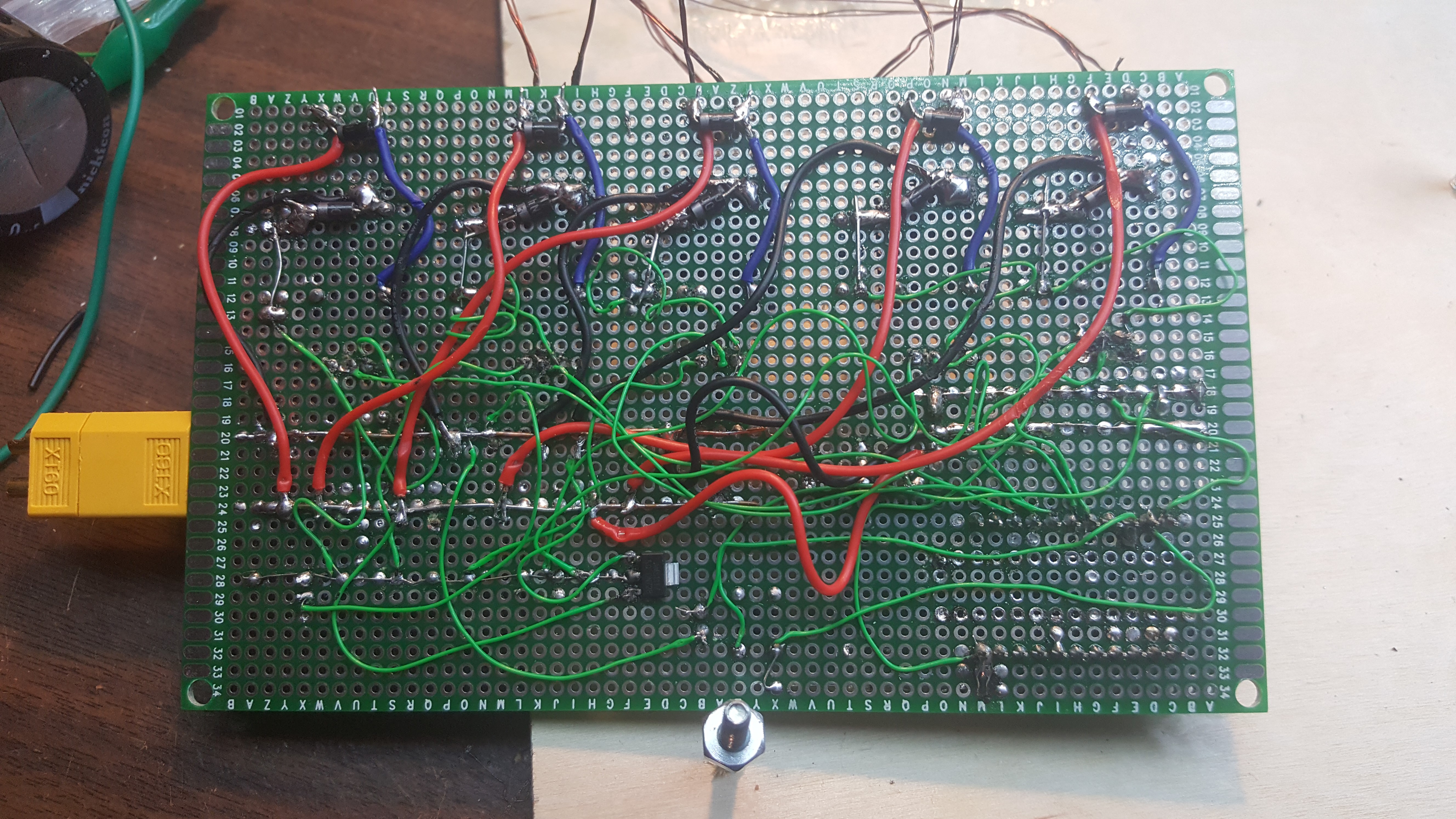
so this is really a project that was born of boredom, i was sitting around one morning and i just wanted to do a project. so i took something I've tried many times. after a few hours of soldering i ended up with a buggy protoboard prototype that seemed to look right. I wrote the code for it in about 20 minutes and gave it a shot... and it worked! twice.... added some flyback diodes to every coil in the circuit and tried it again with better results. i drew up a schematic to illustrate how each stage is wired and how i have it connected to the micro-controller.
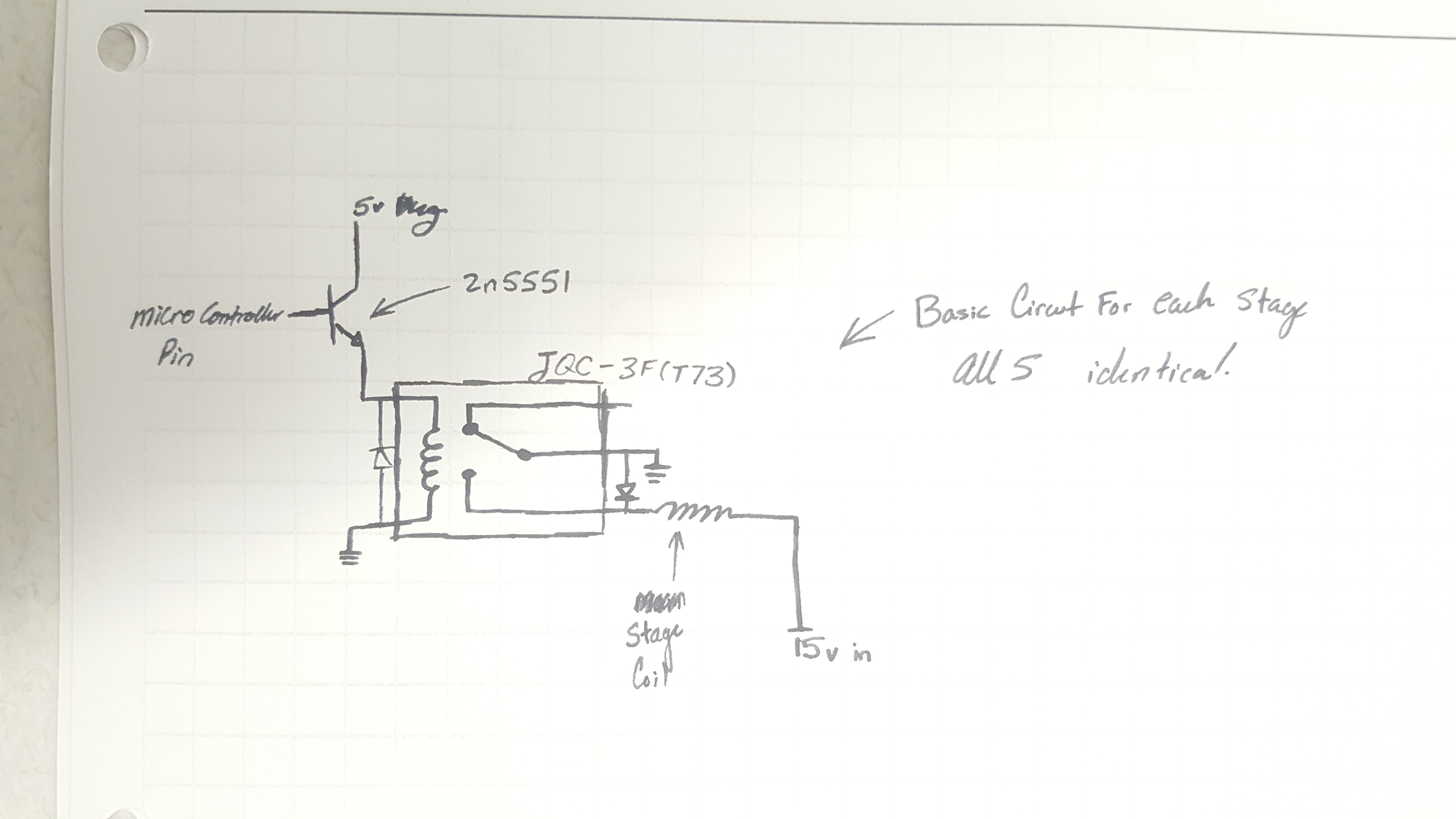
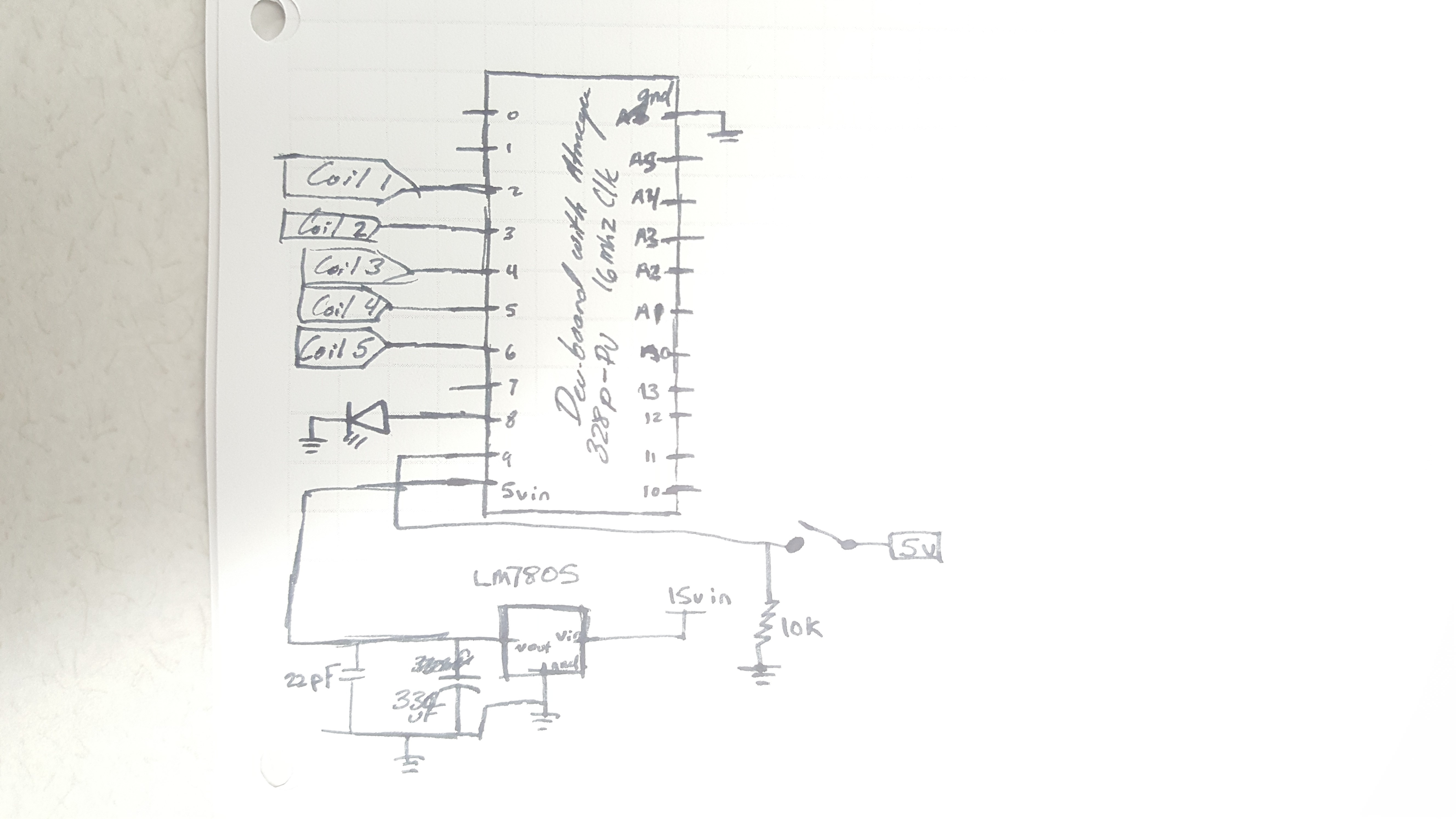
the micro-controller diagram is a bit messy, it uses an Lm7805 linear regulator with a 330uF electrolytic cap and a 22pF ceramic cap on the output. other than that most of the circuit real-estate is composed of the relay circuit which is above, each pin connects to the 2n5551 in its respective circuit.
and that's basically all this mess of wires is
also, the micro controller and the 2n5551s draw from different 5v regulators, the 7805 powers the micro controller while the collector of each transistor is powered by the Vout of a AMS1117. i don't exactly remember why i did it, but it's more work to fix it than leave it.
Discussions
Become a Hackaday.io Member
Create an account to leave a comment. Already have an account? Log In.