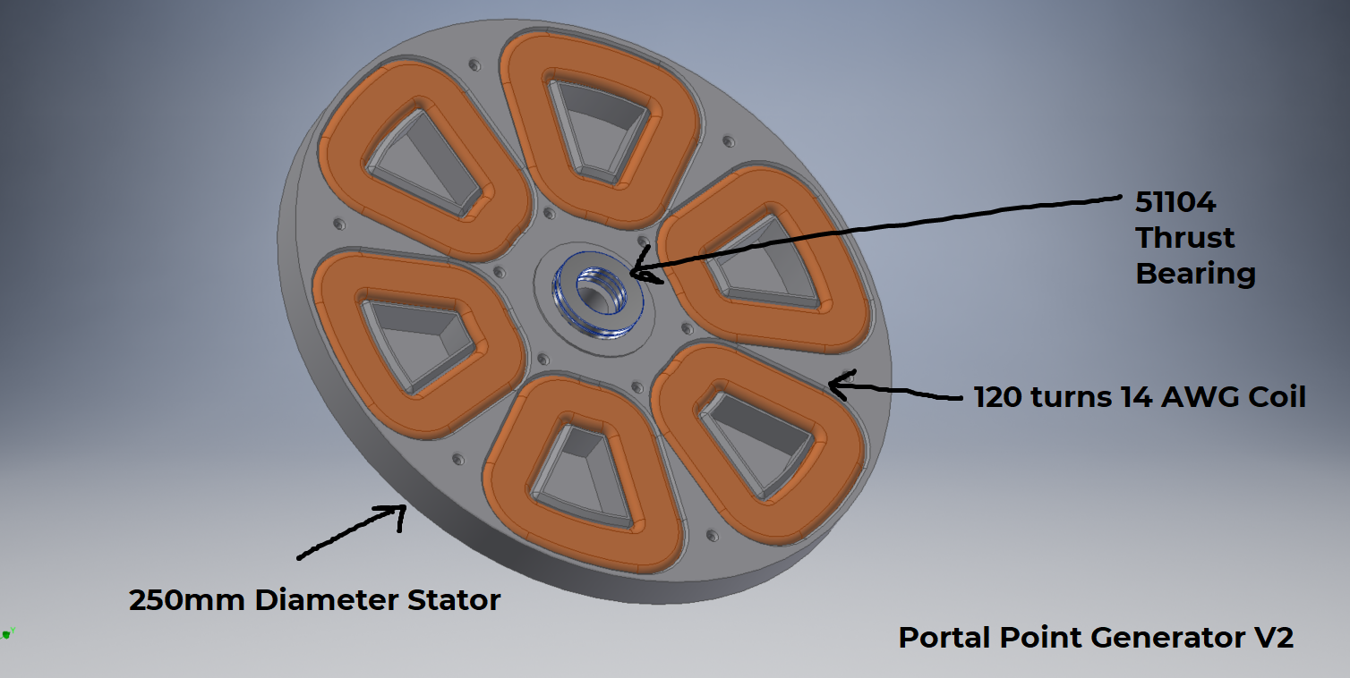
 Its time to go big or go home. Portal Point V2 is going to be a 500W generator, while still trying to be compact enough to fit on a commercially available 3D printer. I'm still using the same 40x20x10 N52 grade magnets, but increasing size of the coils.
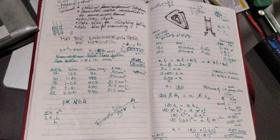
According to my ( very dirty ) calculations I need about 120 turns on 14 AWG copper, to keep resistive losses at a minimum. Ill explain the calculations later, but I'm working on the following assumptions to end up atleast at a 500W 12V generator:
1) Another 3 phase generator, that uses 3 coils instead of 2 per phase claimed 800W 12V using 14 AWG wire of 80 turns. it used slightly larger 52 grade magnets
2) To determine the optimum packing, area of the coil etc, I approximated the of the wire to be a square of side equal to the diameter, so i have a size I can start CAD modelling with. I didn't no any other calculations other than that with this approximation
With that, I came down to a coil of 120 Turns, and a stator of diameter 250mm which can house 2 coils per phase.
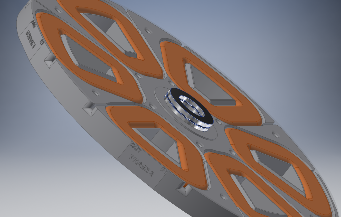
I decided to use a couple of thrust bearings to keep the distance between the rotor and stator constant, that differ from the previous design that can to be fastened to the drive shaft to maintain proper clearance. It was a pain to assemble.
I'm looking at DFA as a side goal for this version.

I labeled the coils as well, so i'm sure of the wiring.
 Vijay
Vijay
Discussions
Become a Hackaday.io Member
Create an account to leave a comment. Already have an account? Log In.