 Tim Savage
With the micro non-responsive it's on to checking if the other components are still working, I've previously determined that the 5V power supply is working, next a check of the various daughter boards to ensure they are all still functioning as well as documenting the functions of each pin.
Input Board
First up the input board, this has the code MT2F15-5A and connects to the P2 connector on the main board.
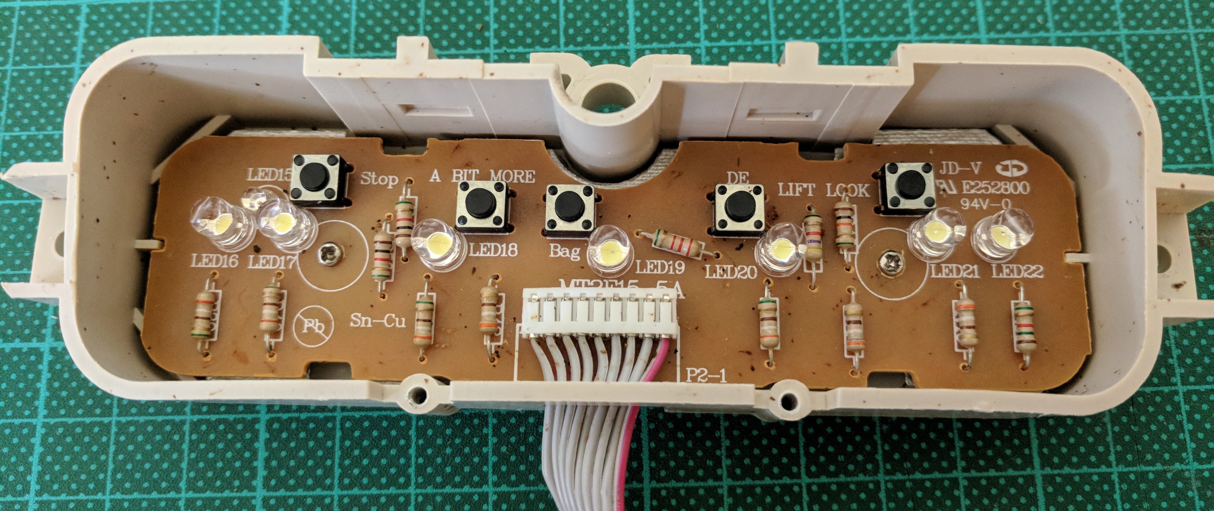
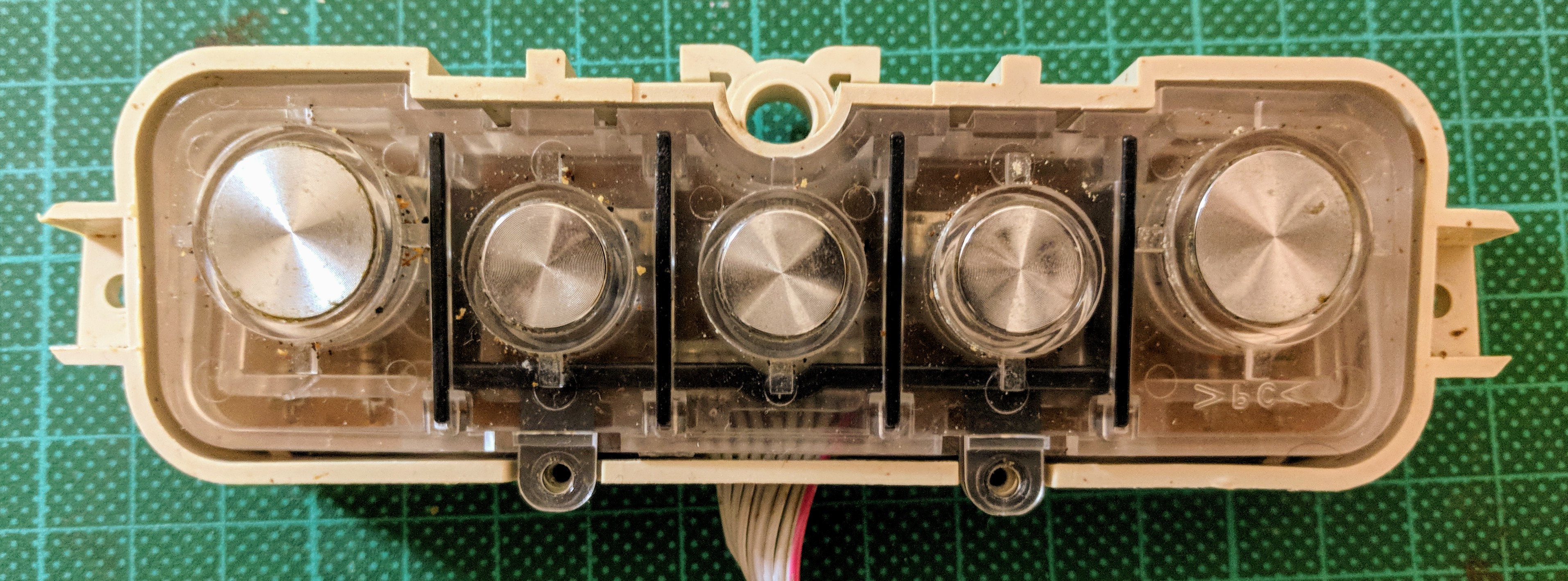
This board is neatly packaged into a plastic unit that screws into the top of the case providing the input and state display. The clear plastic also doubles as a lightpipe to illuminate the rings around each button.
Nothing particularly interesting here, all LEDs have current limiting resistors and if you look closely the resistors increase in roughly powers of two to indicate which button is pressed using 2 wires. The design however, only allows for a single buttons pressed state to be determined with the left most button being favoured.
| Pin | Usage |
|---|---|
| 1 | Button +5V |
| 2 | Button sense. The measured resistance between pins 1-2 with each button pressed: Stop (Toast/Cancel) - 0Ω A Bit More - 1KΩ Crumpet - 2KΩ Defrost - 4KΩ Lift And Look - 8KΩ No buttons - 18KΩ |
| 3 | LED 15 |
| 4 | LED Common |
| 5 | LED 16 & 17 |
| 6 | LED 19 |
| 7 | LED 20 |
| 8 | LED 18 |
| 9 | LED 21 & 22 |
Everything seems good on this board, all the LED's light up and buttons work correctly.
Progress Bar
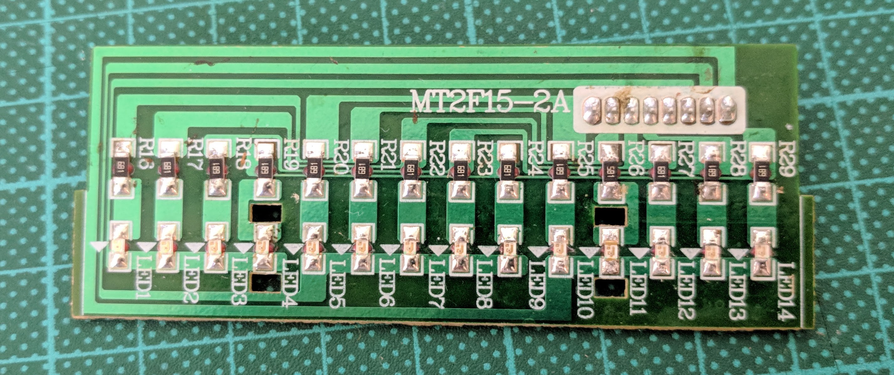
This board is just an LED matrix. This board has the code MT2F15-2A and connects to the P3 connector on the main board.
Pin to LED matrix
| Pin | 6 | 7 | 8 |
| 1 | LED 5 | LED 10 | |
| 2 | LED 1 | LED 6 | LED 11 |
| 3 | LED 2 | LED 7 | LED 12 |
| 4 | LED 3 | LED 8 | LED 13 |
| 5 | LED 4 | LED 9 | LED 14 |
On the board again it looks to be largely good, although LED 11 is dead.
Control Board
This is where the mains pixie wrangling is performed via a series of relays. The relays control the heating elements and lift motor. The pin out of this board is still a work in progress as it has the high voltage wires connected directly to it and is not easy to remove from the chassis. This board has the code MT2F15-4A and connects to the P1 connector on the main board.
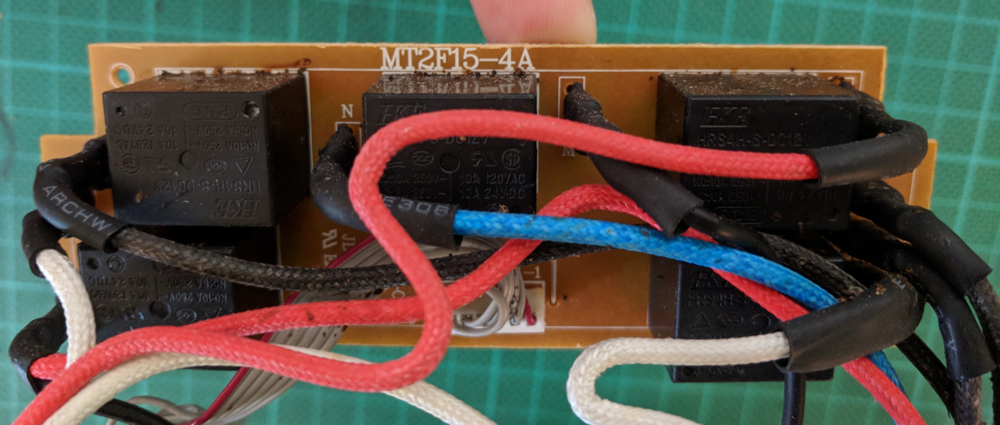
The middle relay controls the Lift motor. While the relays on each side control the four elements.
| Pin | Usage |
|---|---|
| 1 | +12V (roughly) |
| 2 | Ground |
| 3 | +5V - Centre heating elements only (turns off outside elements) |
| 4 | +5V - Motor on |
| 5 & 6 | +5V - Elements on, both are required to turn the heating elements on. |
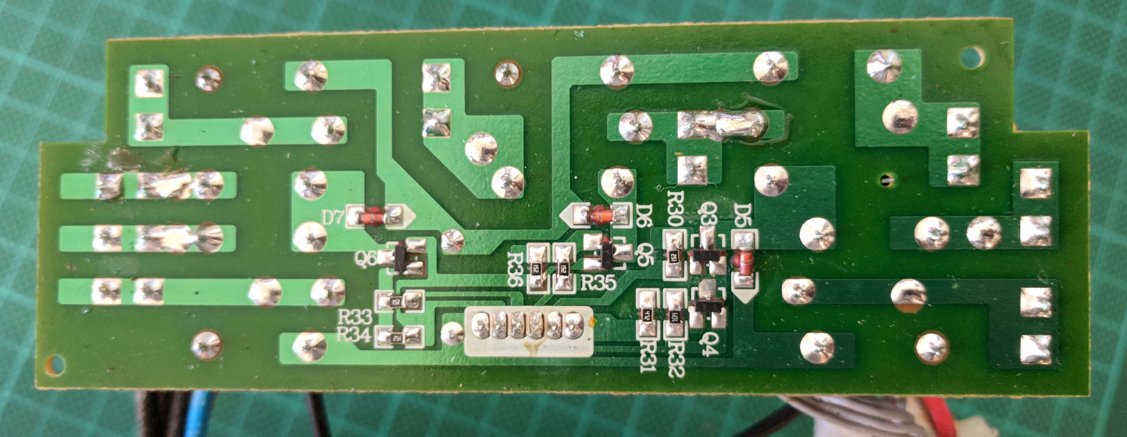
Main Board
The main board holds the power supply, toast level control, buzzer and MCU. The board has the code MT2F15-1A, in addition to connecting to the daughter boards it also has a power supply input (~13V AC) and inputs from the limit switches used to determine the position of the lift motor. Note in these photos the ceramic oscillator has been removed.
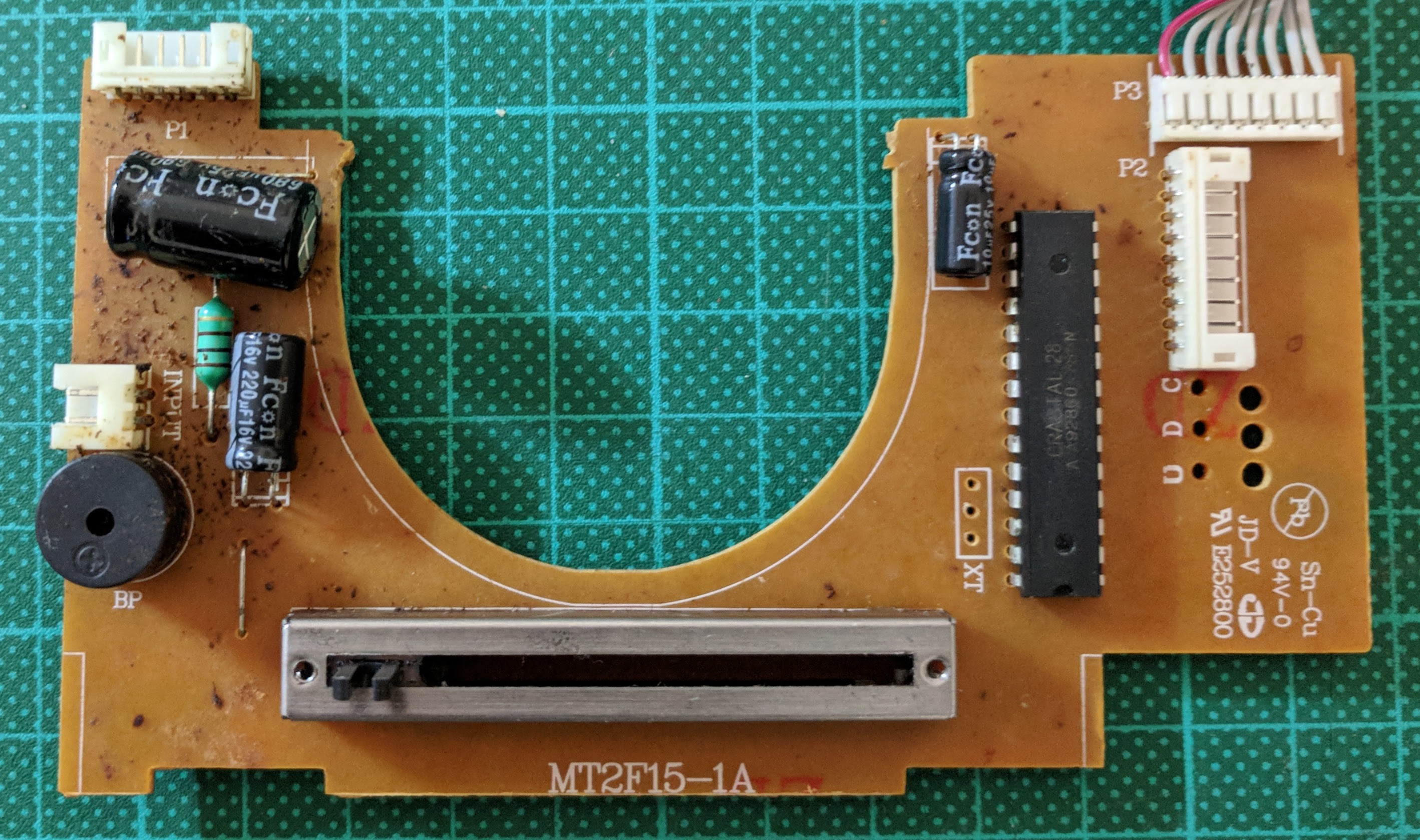
The MCU is a Crastal 28 (spelling is correct). The large cutout is to allow for the motor.
With some Google Foo and results filtering the MCU provided a lot of information about the origins of this product. The "Crastal" MCU is either a custom or custom labelled part for a company called Crastal Technology based in Shenzhen China. The company does product design and manufacturing for many big brands including Breville (they also appear to have a number of their own products including Sauna Pants?!?).
The MCU pinout is fairly straight forward
| Pin | Usage | Pin | Usage |
|---|---|---|---|
| 1 | Connector P3, Pin 6 - LED 1-4 Common | 15 | Connector P2, Pin 9; Connector P3, Pin 1 |
| 2 | Connector P3, Pin 7 - LED 5-9 Common | 16 | Connector P2, Pin 8; Connector P3, Pin 2 |
| 3 | Connector P2, Pin 4 - LED 15-22 Common (Input board) | 17 | Connector P1, Pin 6 - Heating elements on |
| 4 | Connector P2, Pin 3 - LED 15 | 18 | Connector P1, Pin 3 - Centre elements only |
| 5 | Buzzer | 19 | Connector P1, Pin 4 - Motor |
| 6 | +5V | 20 | Connector P1, Pin 5 - Heating elements on |
| 7 | GND | 21 | AREF? (+5V) |
| 8 | TBA | 22 | +5V |
| 9 | Connector P2, Pin 2 - Buttons (Analog) | 23 | XTAL |
| 10 | Up limit switch | 24 | XTAL |
| 11 | Down limit switch | 25 | NC |
| 12 | Connector P2, Pin 7; Connector P3, Pin 3 | 26 | NC |
| 13 | Connector P2, Pin 6; Connector P3, Pin 4 | 27 | NC |
| 14 | Connector P2, Pin 5; Connector P3, Pin 5 | 28 | Connector P3, Pin 8 - LED 10-14 Common |
From this we can see that all of the LEDs are in a matrix not just the progress LEDs. The pinout is "similar" to a ATMega128 which I might end up dead bugging to the board and soldering wires over into the appropriate pin locations.
Next time the electro-mechanical and high voltage components.
Discussions
Become a Hackaday.io Member
Create an account to leave a comment. Already have an account? Log In.