 Tim Savage
In this part I investigate the high voltage and mechanical side. All of the high voltage circuits are controlled via the relay board MT2F15-4A (while working out a schematic for this board I all filled out all the pin details from Part 1).
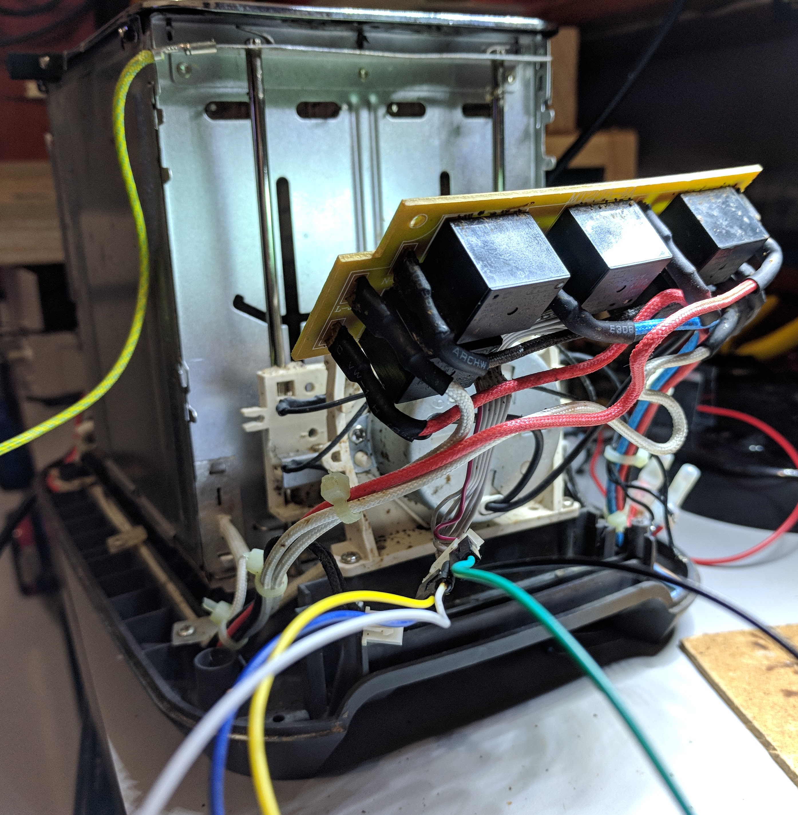
This board is hard wired into the unit and I didn't really want to remove it, I did however, wire up a quick control mockup on a breadboard and use my bench-top power supply to power the low voltage side. Next I (very carefully!!!) applied mains power to board to determine the exact function of each relay. This also confirmed that all of the heating elements are working and that the motor to raise and lower the lifter runs.
Missing from this picture is the plastic bracket that sits above the motor frame, this encloses the high voltage relay board. The bracket also provides structural rigidity when the motor is in operation (see the video at the end of this log for it running).
 The outcome is the following schematic describing the operation of the unit. Low voltage side to the left and the mains side on the right.
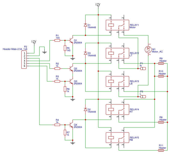
| Pin | Usage |
|---|---|
| 1 | +12V roughly, this is actually the raw voltage out of the rectifier, probably closer to 16V. |
| 2 | Ground |
| 3 | Centre only, applying 5V turns the outer heating elements off. Controls both NC relays 4 & 5. |
| 4 | Motor on, applying 5V turns on the motor. Controls relay 1 |
| 5 & 6 | Heating elements on. This looks to be a safety feature, both pins require 5V to turn on both NO relays 2 & 3. These switch both the Active and Neutral. |
And finally the mechanical motor lift. Note the two limit switches tripped by the rotating cam.
Discussions
Become a Hackaday.io Member
Create an account to leave a comment. Already have an account? Log In.