 Wasim Sahu
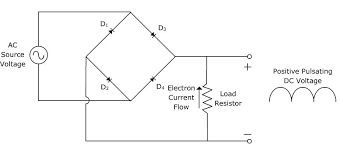
BUILDING THE BRIDGE RECTIFIER:
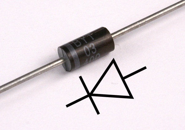
Ok, so for those of you who do not know how to read a circuit diagram, those 4 line segments with arrows on them represent diodes. The arrows always point to the side of the diode that is marked, also known as the positive side. If you have small, rectangular diodes like me, the positive sides are not marked by coloration, but rather small, engraved lines/notches. By following this diagram, you should be able to create the bridge diode.
WIRING THE BRIDGE RECTIFIER:
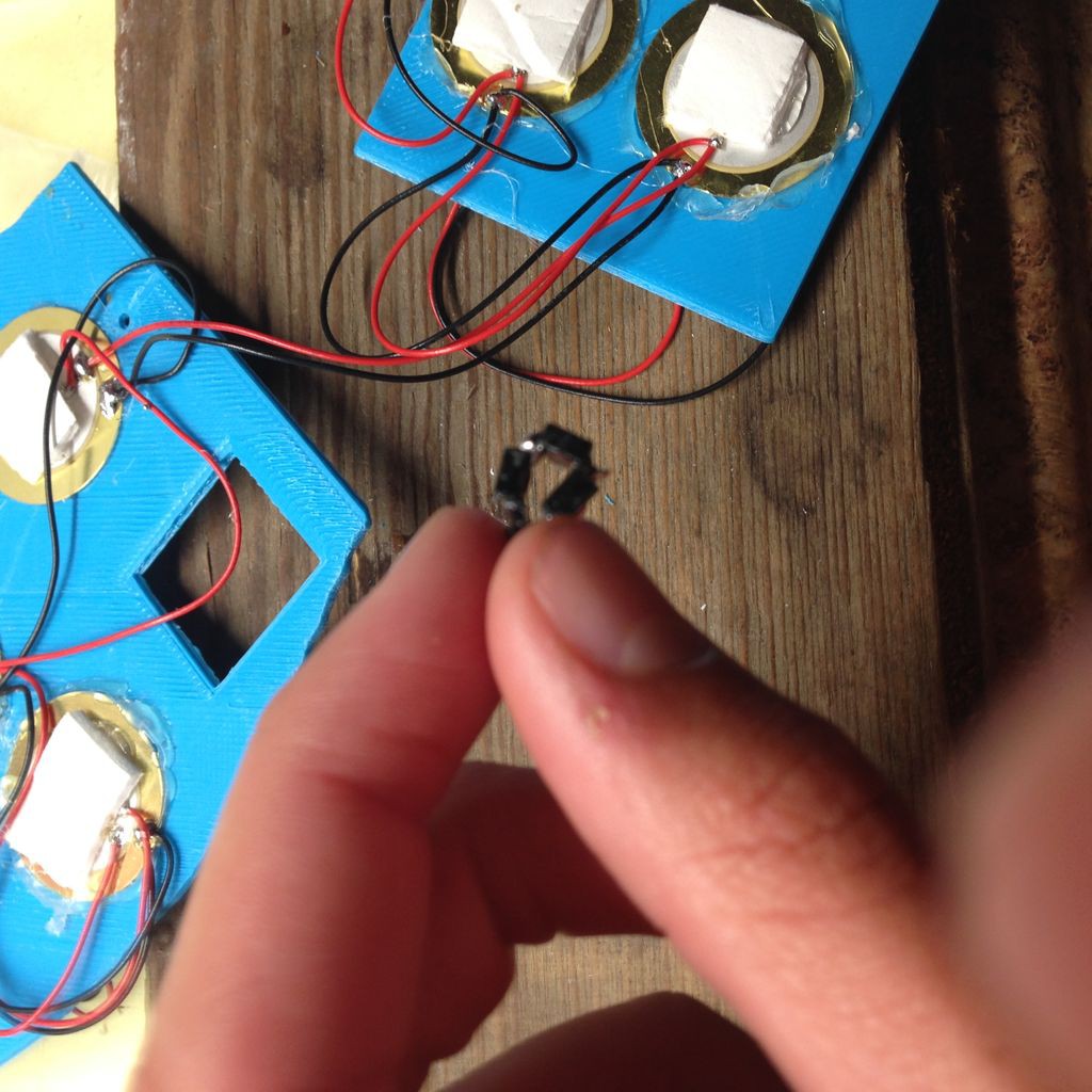
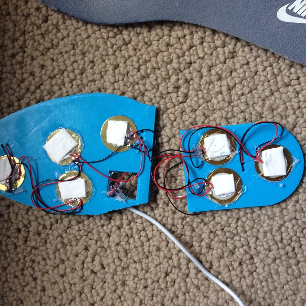
- Wire the piezo element wires to the bridge diode according to the circuit diagram. Since the current is AC, the position of the wires are interchangeable, as long as they connect to the correct diodes in the diagram.
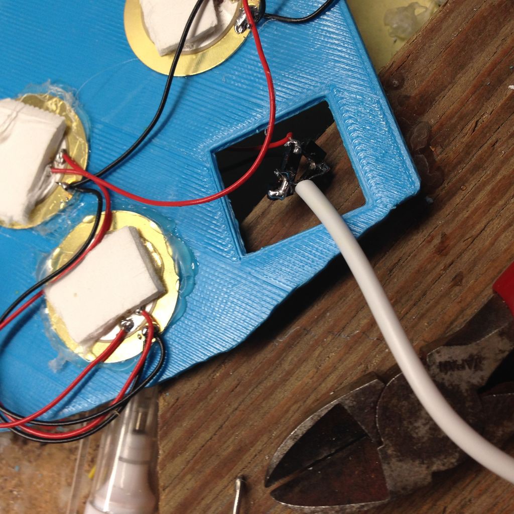
- Strip the usb charge cable that came with your battery pack to reveal the internal wires.
- For the purpose of this project, we will only need the red and black wires, so strip those as well.
- Twist the frayed wire strands of each wire, and tin them with solder
- Solder the wires to the bridge diode accordingly. Be sure to check polarity since DC voltage has positive and negative terminals.
- Hot glue the connections to prevent the wires from breaking off.
Discussions
Become a Hackaday.io Member
Create an account to leave a comment. Already have an account? Log In.