 Nicolò
-
Making the Baseboard
07/14/2018 at 08:26 • 0 commentsThe baseboard provides the power to the whole unit and also manage the IOs using the ATmega 328.
The whole project run on 3V. This is due to some spare working relays i got from my old broken thermostats. It is a latching one with double coils running at 3 volts.
Unfortunatly the ATmega can't safely run at 16Mhz at that voltage. According to the datasheet I must choose a lower frequency!
Taken from arduino forum, more details in the 328p datasheet To make this project easier (for me) I decided to use a 8Mhz clock so i could directly use the Arduino Pro mini bootlaoader.
During the development phase of the Baseboard lots of changes were made. The most important one was the "Solid PSU" as I like to call. The power brick I choosed was a Recom Power RAC03-05SGA, it is a 3W 5V power supply. I than would used a 3.3v linear regulator like a LM31117-3.3 for the relay and the microprocessor.
But than I had some newer ideas: Make the board compatible with some modules that can add more functions. The initial ideas was: KNX for domotics or CAN bus. Than I started to think about a GSM/GPRS module.
Unfortunatly to do so I needed more space on the board, So i moved to a more stronger Recom Power 919-RAC05-05SK. This one can output 5V up to 1A. And due to the local regulator for the 3.3V I can also have external modules running at 5V while the AVR still run at 3.3V. With this last consideration I added the IO header, the mount holes for the module and I moved the components around.
I'm still not sure if this PSU is powerfull enough for my needs. In case l'll make another revision of my board. But in that case the problem is the fact that off the shelf PSU modules with lots of power are too big for my dimensional constraints!
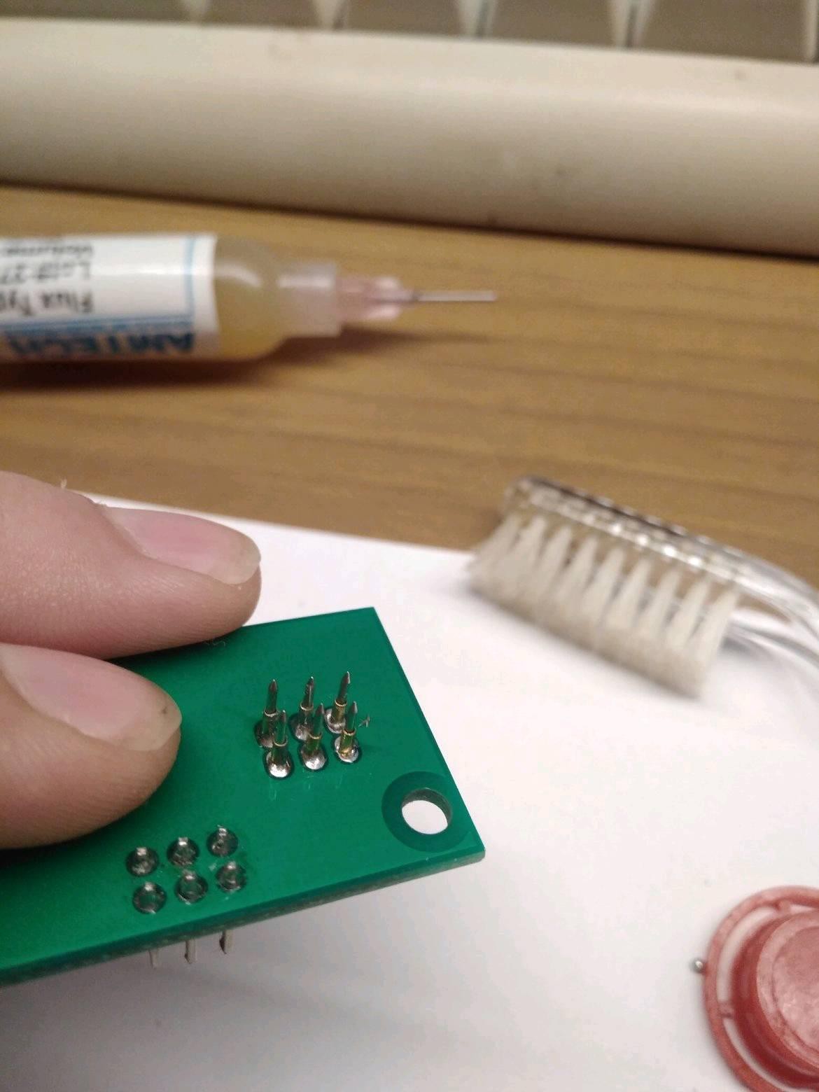
For programming I added the ISP pads on the board, So with a special clamp I should be able to program the uC. The clamp is just a module that locks into position on the holes and with pogo pins makes contact with the PCB. I can also provide power to the board via that, So i don't have to hook it to mains to program it.
![]()
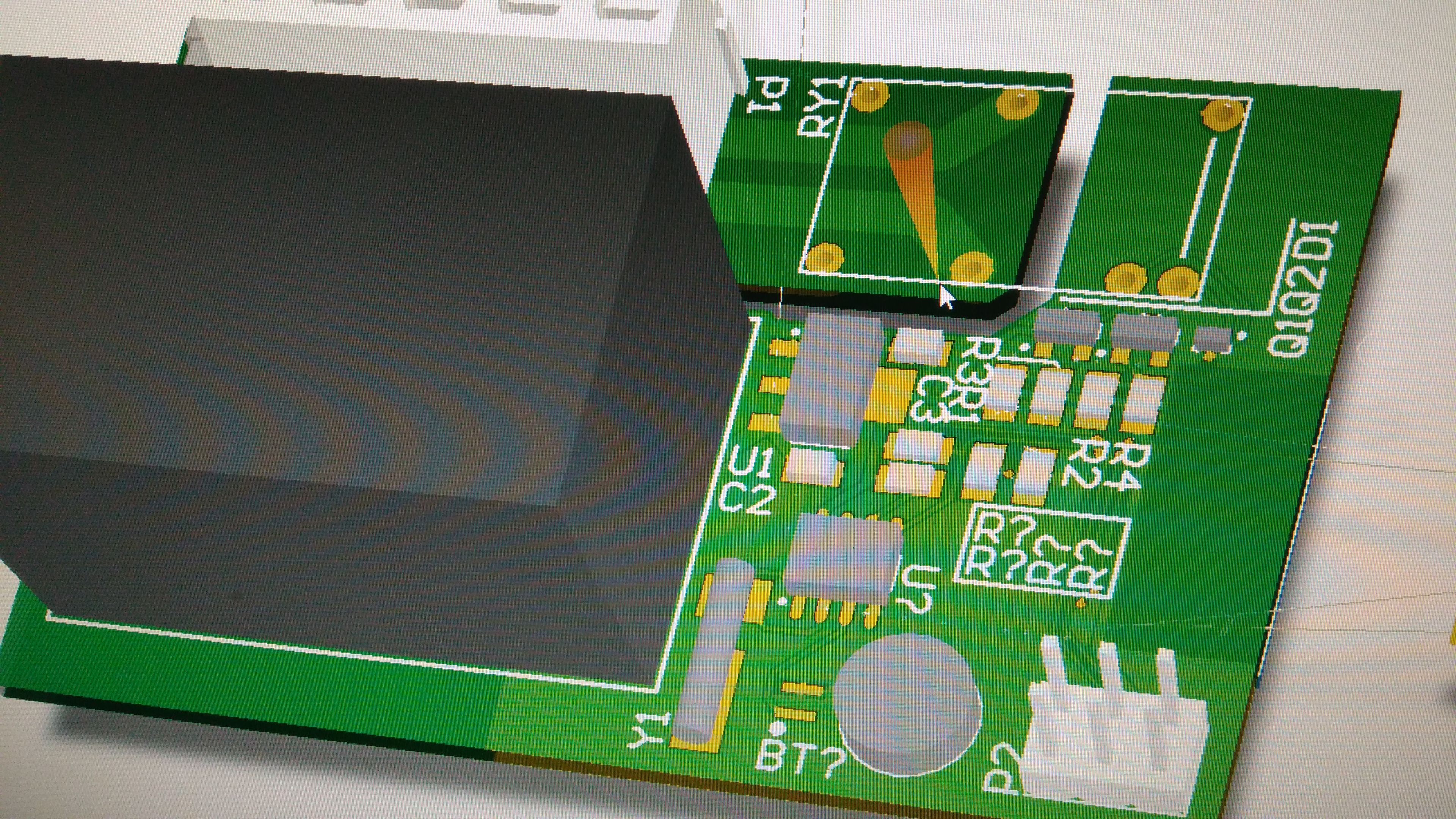
With those new additions I designed my first board revision:
![]()
But before ordering the PCB prototype I had to complete the GSM module... "spoiler alert:" which doesen't works!
-
Backstage
07/11/2018 at 18:45 • 0 comments![]()
The development phase started long time ago. Initially I wanted to use an esp8266 to manage a display and input sensors. It had WiFi and it could be perfect for what I needed. I started to design a board around the ESP-12 module but the ESP don't have enough gpios for my needs. (Displays uses SPI busses and a lot of lines to control)
At that point I was starting to design a proper board size, here in italy the electronic stuff is inserted into 503 boxes. The sizes are small but not that small!
![]() Now I moved to a ATmega 328P, and I decided to add an IO header to add more functionality later.
The module have acces to all most important gpios of the ATmega like interrupts and serial.
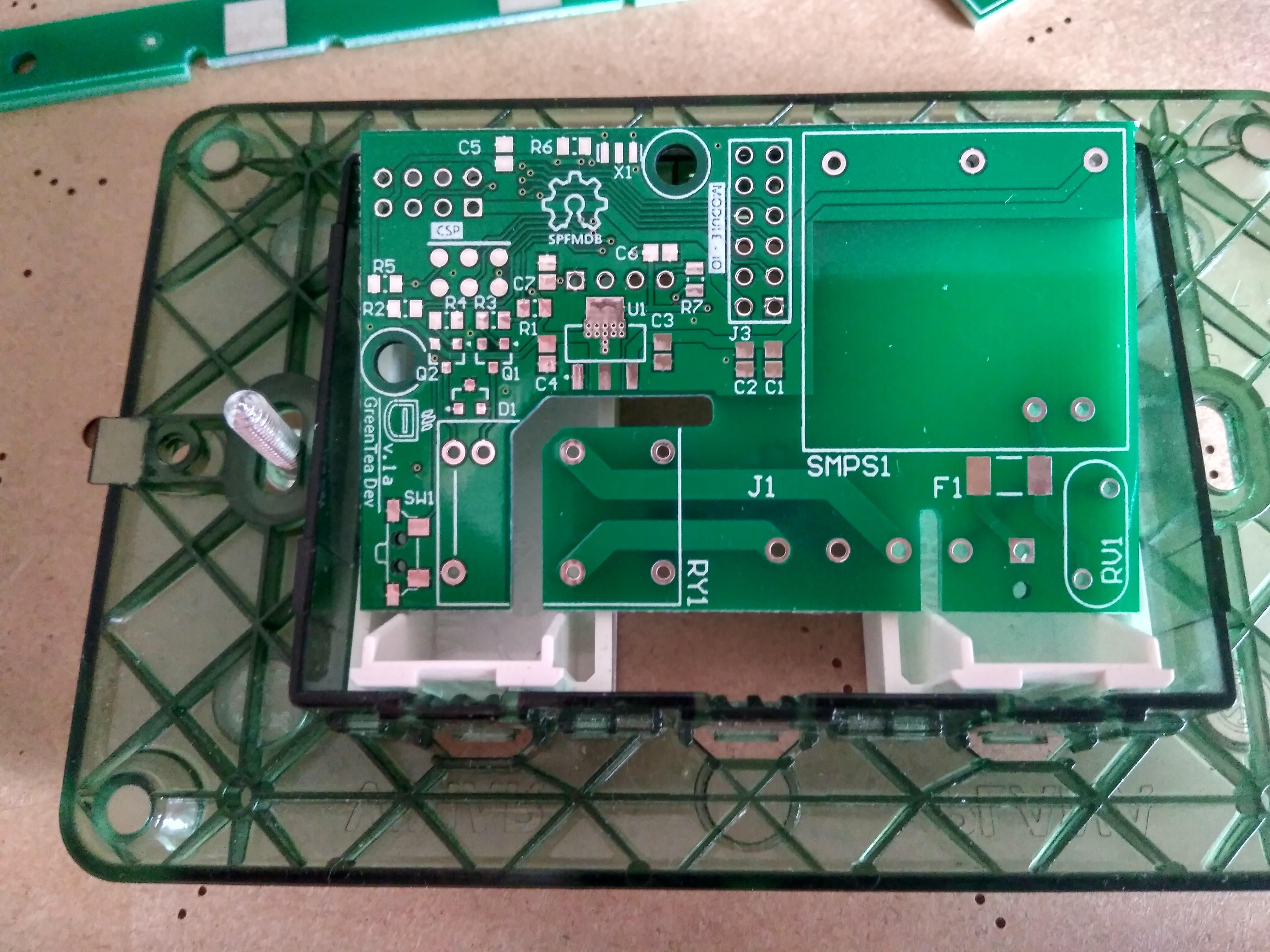
On the back of the baseboard an header is used to connect to the front board with the most important stuff :)
Now I moved to a ATmega 328P, and I decided to add an IO header to add more functionality later.
The module have acces to all most important gpios of the ATmega like interrupts and serial.
On the back of the baseboard an header is used to connect to the front board with the most important stuff :)
FCThermostat: Another overengeneered IOT device
A new way of thinking to a IOT thermostat:


 Now I moved to a ATmega 328P, and I decided to add an IO header to add more functionality later.
The module have acces to all most important gpios of the ATmega like interrupts and serial.
On the back of the baseboard an header is used to connect to the front board with the most important stuff :)
Now I moved to a ATmega 328P, and I decided to add an IO header to add more functionality later.
The module have acces to all most important gpios of the ATmega like interrupts and serial.
On the back of the baseboard an header is used to connect to the front board with the most important stuff :)