After finding out that the project could be accomplished in a "humanly" simple way, unfortunately, there was not enough time left to acquire the parts - a bunch of 100uF+ ceramic capacitors and a ultralow-consumption RTC. (Btw., turns out, theadvertised 40nA RTC module is not yet available from the "usual outlets", but another module consuming only 60nA is, at a reasonable price, and it even features a calibrated-RC-mode when the consumption drops to mere 17nA!) So, using a couple of 10uF 0805 ceramic capacitors at hand, and the built-in RTC of STM32L476 on the L4-DISCO board, I proceeded at least with a basic proof-of-concept project.
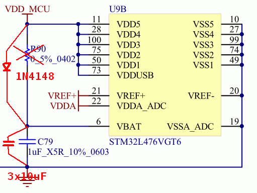
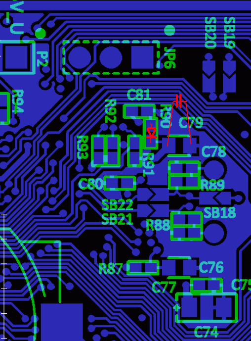
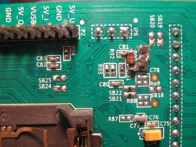
The VBAT pin, supplying the built-in RTC in mcu, on the DISCO board is not brought out separately but is connected to VDD - luckily through a resistor, R90. This has to be replaced by a 1N4148 diode, and the 10uF capacitors have to be added in parallel to the existing 1uF C79:

1N4148 has a leakage of a few nA at 3V reverse voltage. While charging (i.e. mcu is supplied through VDD), mcu supplies the RTC internally, thus no current flows through VBAT, so - after several hours of sunlight/charging even the dielectric-absorption-capacitance of the storage capacitor is fully charged, so only leakage flows through the diode, which we hope will be only a few nA. At that current, the forward voltage drops towards tens of mV, which is something we probably may sacrifice - it's not worth to experiment with exotic low-leakage transistors, or even relays, in place of a simple diode.

A good thing about the ST devboards such as the DISCOs, is, that ST provides extensive documentation, including schematics, Gerber files and even a detailed BOM - so modding them is relatively easy.

While we assume enough power for the "normal" run during daytime, there's no reason to waste energy if it can be avoided. So the firmware first initializes the internal RC-oscillator-based clock (MSI) and switches it into 400kHz mode to reduce consumption, which enables to switch from the standard internal regulator to a low-power one. These few simple steps brings basic runtime consumption down to cca 250uA. This can be conveniently measured by removing the jumper from JP5 and routing an ammeter from any of the outer pins to the middle pin - the middle pin of this jumper connects directly to the mcu's VDD; the ON position pin goes from the onboard current measurement and the OFF position pin is directly the power supply input bypassing the current measurement (using the onboard extra microcontroller for measuring current involves talking it through I2C in a protocol which is not very well described and has to be mostly extracted from the demo sources, so I left it for another time).
Then the firmware checks, if the 32.768kHz LSE oscillator is already running and if RTC is enabled - if yes, everything is left as it is; if no, the oscillator is started, RTC enabled and initialized. There is no provision to adjust time, yet; the joystick on the DISCO board is to be used for this purpose.
Then the LCD is initialized, and then the main loop is entered. In it, the current time is read out of RTC and displayed, and then the mcu goes to sleep until the RTC ticks and wakes it up - this further reduces consumption to some 50uA. Even lower levels of consumption should be possible to be achieved, down to maybe some 10uA (including the LCD's consumption), but this should be enough for the first experiments.
I then took a solar cell salvaged from an commonplace solar lantern, with moderate illumination this one easily achieves 2-3V, sufficient to run the module. As the RTC consumes around 300-500nA (depending on voltage, but also on the particular crystal and surrounding circuitry), the 3x10uF capacitors, after being fully charged, should be able to supply it for cca 100 seconds or roughly 2 minutes (the RTC works down to 1.5V, and the current consumption with voltage is nonlinear, so endurance is slightly longer)
 Jan Waclawek
Discussions
Become a Hackaday.io Member
Create an account to leave a comment. Already have an account? Log In.