deʃhipu
-
Bigger Matrix
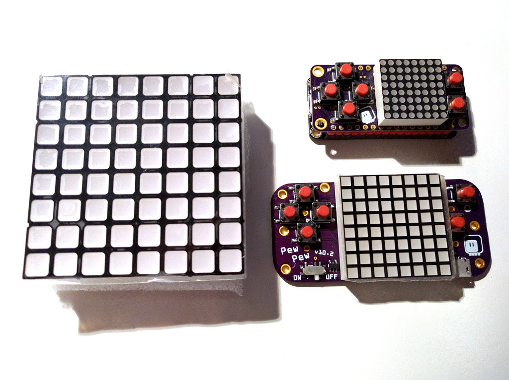
08/26/2018 at 20:35 • 1 commentSo I found this nice 60×60mm matrix in my drawer:
![]()
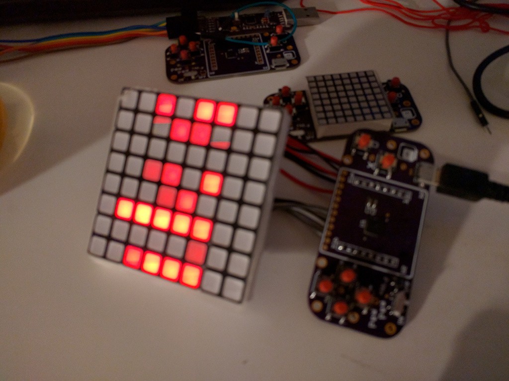
(I think that I previously mentioned a bi-color matrix of similar size.) In any case, it's a great temptation for designing a PCB for a bigger version of the PewPew. It would of course be more expensive (the matrix I'm using right now is a kind of sweet spot, being the cheapest and the easiest to source), but maybe it would make sense to have one like that during the workshop, so that the teacher can show things to the whole group from a distance. Whatever the justification, for now I just wired it to the small PCB with wires:
![]()
It works perfectly fine! I could even mount it in some kind of box, with the PCB with the buttons below it, to have a pretty convenient device. For now this is just an experiment, but it's good to know that I could make such a big version. Maybe one day it will become a badge for some conference, who knows.
-
Tutorial
08/24/2018 at 16:51 • 0 commentsIn the mean time I was also working a bit on the documentation. I have restructured the ReadTheDocs website a bit to allow for different devices, and I have written a simple Bouncing Ball Tutorial. Of course that is not enough to actually run a workshop, but it's enough to get you started writing your own game, hopefully.
-
PewPew X Assembled
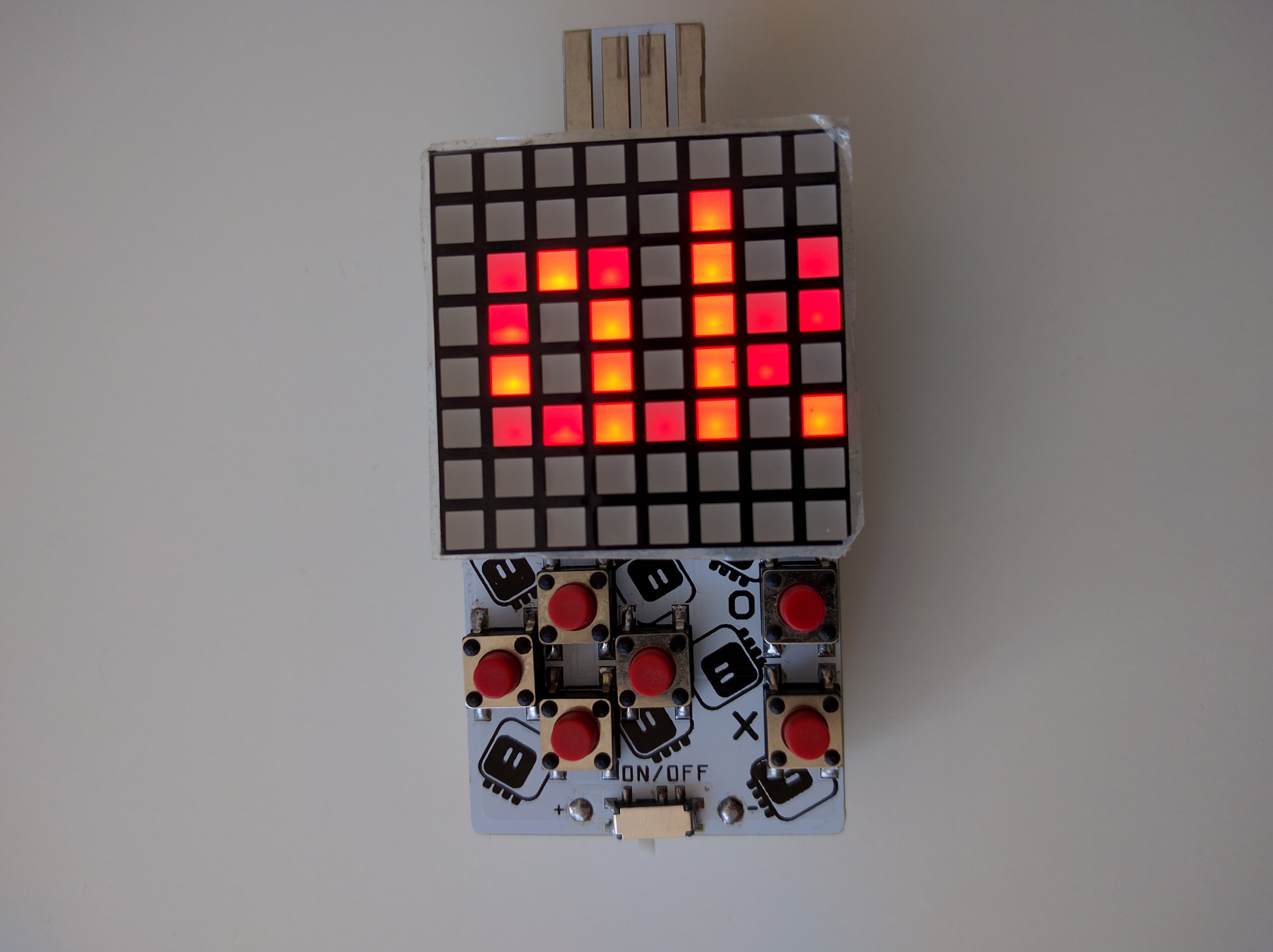
08/23/2018 at 21:25 • 1 commentThanks to the generosity of @oshpark, the PCBs for version 10.2 arrived today. I spent the evening assembling it and updating the code to handle the new button arrangement. Here it is, with the working scrolling text in all its glory:
![]()
Please excuse the potato-cam that can't really catch the colors properly, and the dark photo — it's night in here already.
For debugging, I'm using the optional voltage regulator to power it from USB. I'm still waiting for the battery holders for 2×AAA batteries. Once they arrive, I can also try experimenting with a laser-cut piece that will go on the back around the battery holder, to make the whole thing more comfortable to hold.
I also need to prepare all the materials and start asking fabs for quotes — this will be the final result of all this work for making it cheaper.
-
Version X
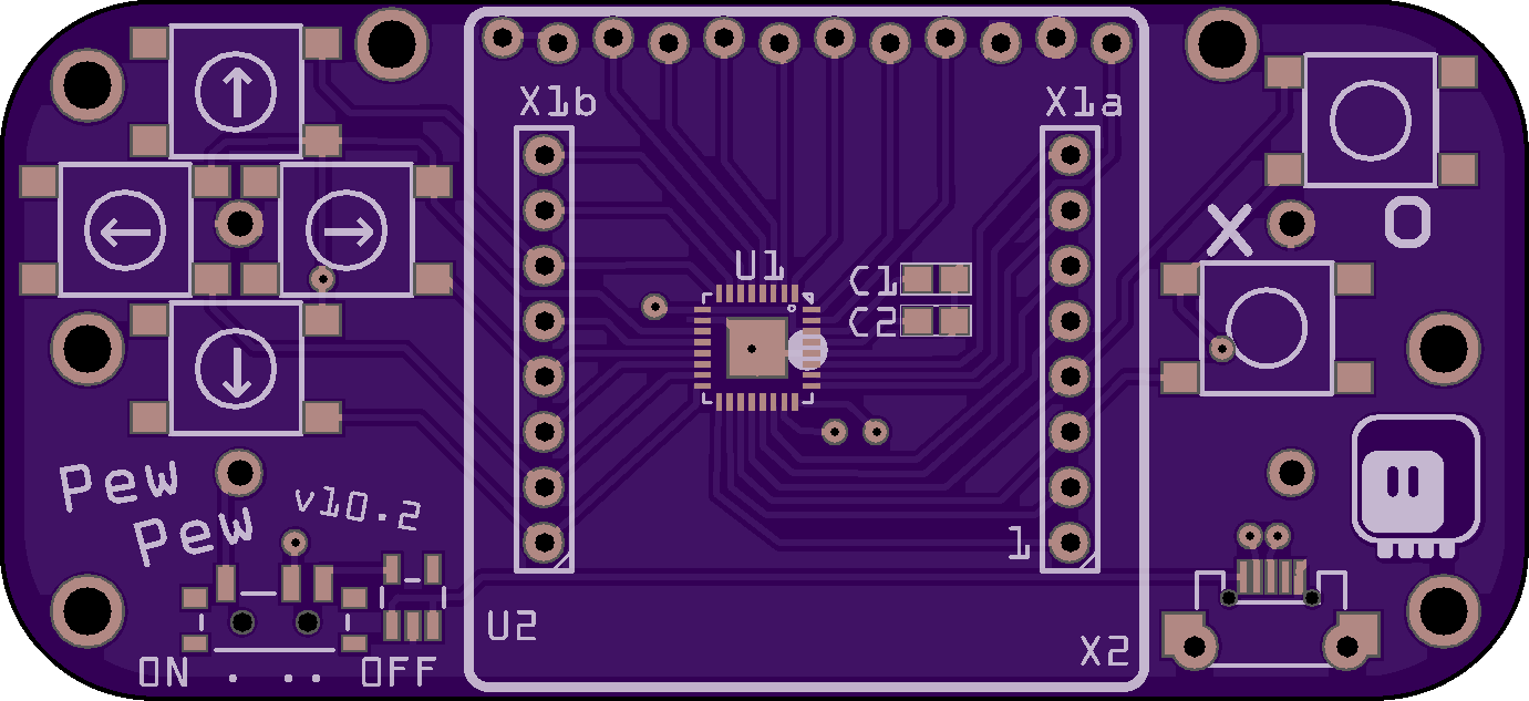
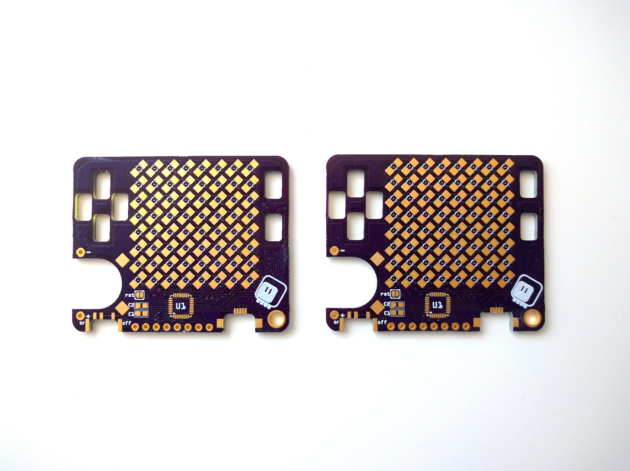
08/16/2018 at 00:32 • 1 commentIt's a kind of anniversary: I have reached the tenth prototype of the "standalone" version of PewPew. Admittedly, not all prototypes have been actually realized in hardware, but many were, and all were ready for it. In any case, I present you the tenth version:
![]()
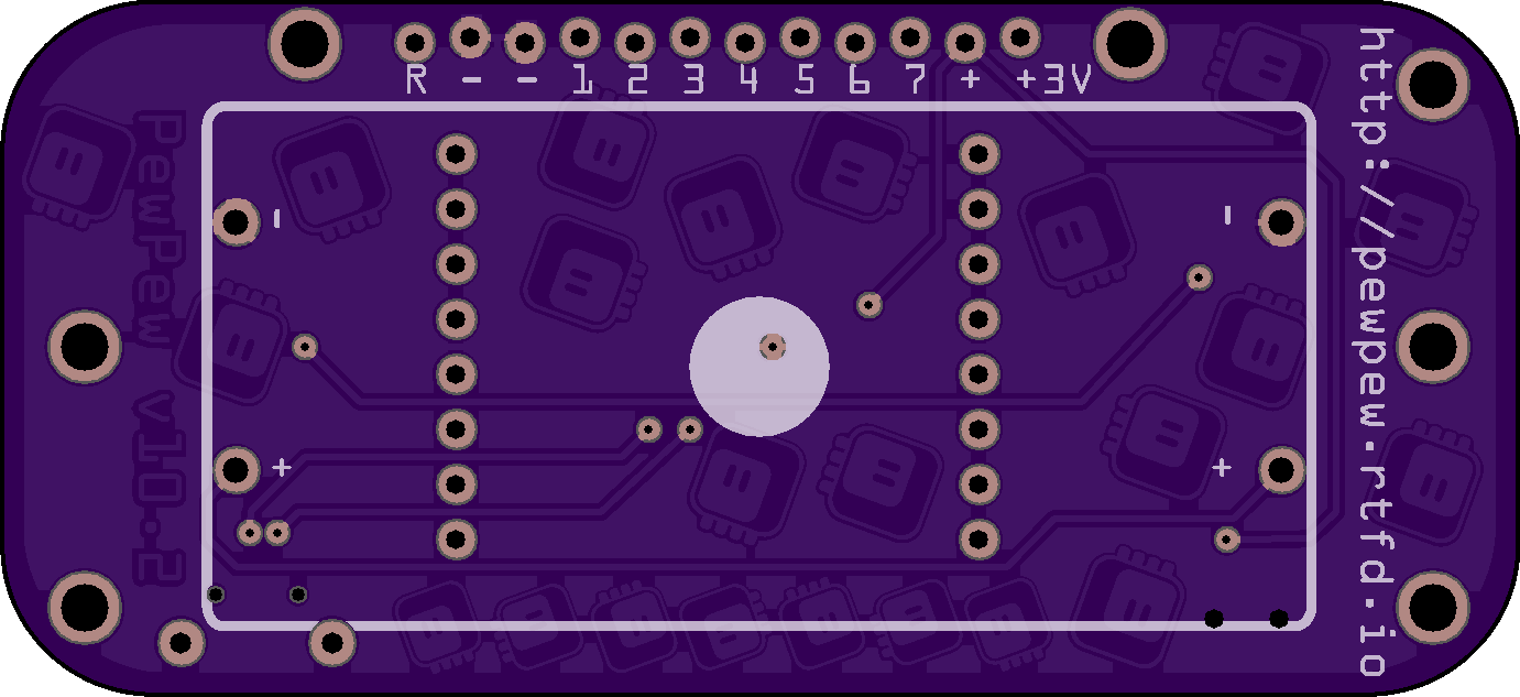
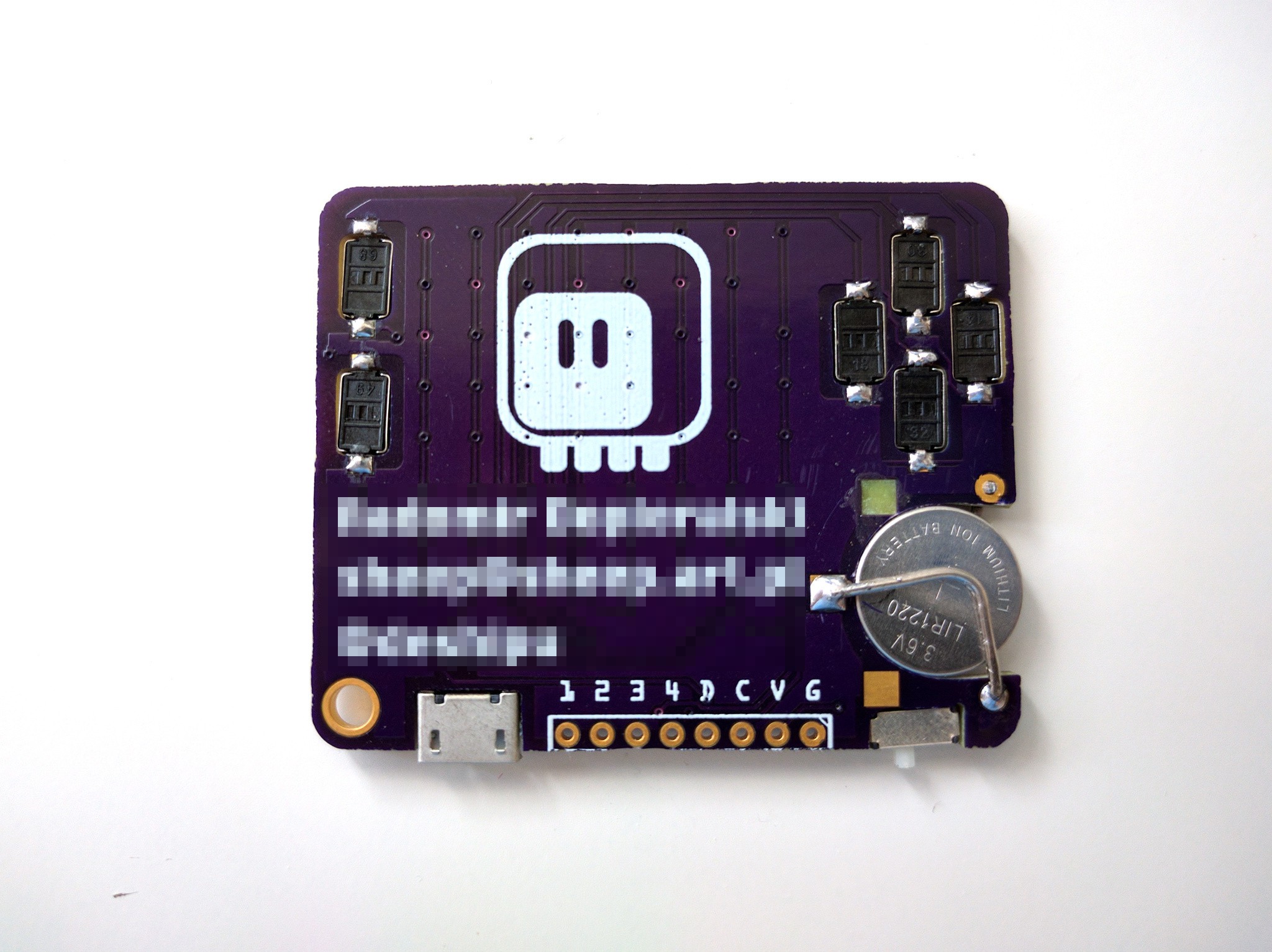
I took some liberties in the design of the back side, since it will be mostly hidden anyways:
![]()
As you can see I narrowed the device back to the 32mm of the LED matrix, and I squeezed the pin header underneath, only accessible from the bottom. I think this makes the whole design more robust, and doesn't much affect convenience. I can put a color sticker on the top edge of the matrix to serve as a legend for the pins.
I'm also considering adding laser-cut pieces on the underside and top, similar to how this year's Hackaday Belgrade badge had. This way it will be thicker and easier to hold. Of course they are optional. I will prototype them with wood for now.
There is another option in there — I added a footprint for a voltage regulator next to the power switch. It will be unpopulated by default, but if you add it, you can use the device without battery, just connected to USB.
The battery holder is for 2×AAA batteries, and I made holes for two versions — because the order of cables coming out of them seems to be mostly random. A 2×AA holder would fit too, but it would cover the pin header, so not recommended.
There are two mounting holes next to the pin header. Those can be used to securely attach any kind of larger add-ons for the device. The laser-cut parts will have a suitable cutout, of course. There is also plenty of holes for either attaching a case, or attaching the device to a larger contraption.
Finally, I made both the power switch and the USB port a little bit recessed — so that they don't stick outside the outline of the board. That should make it easier to carry it in your pocket.
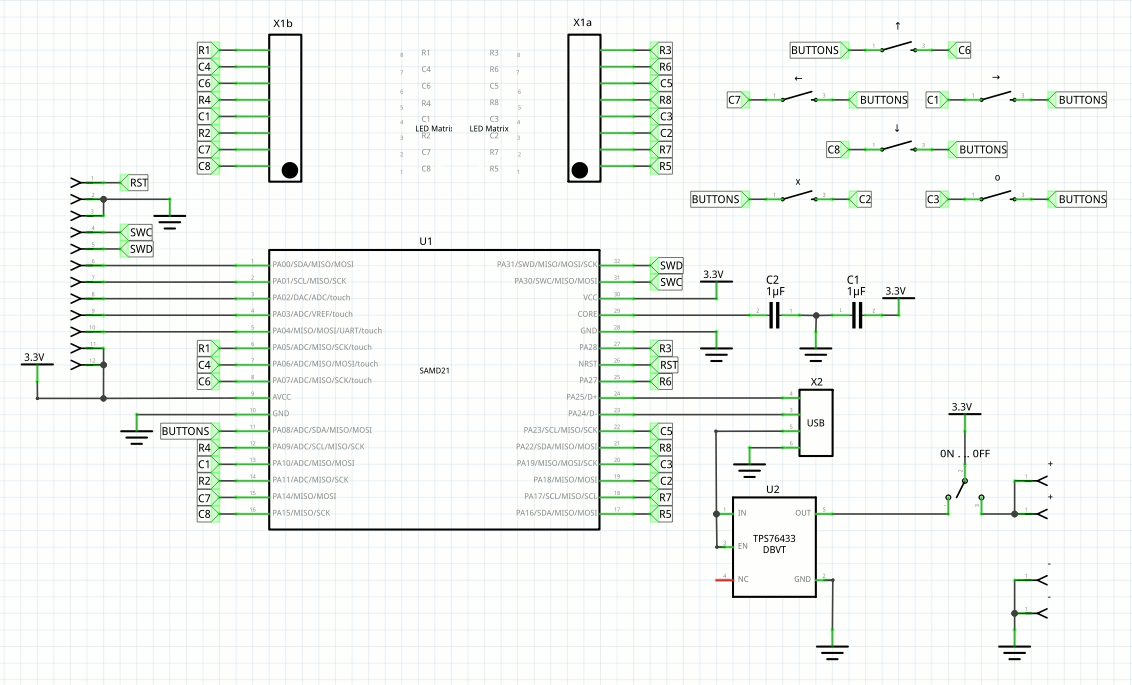
Oh, and I even made a schematic!
![]()
-
Saving Pins
08/14/2018 at 09:15 • 0 commentsAs the prototypes are coming, this device is becoming a pretty nice thing for teaching game programming, which is its main focus. However, wouldn't it be great if it could also be used for hobby electronics projects, like the micro:bit or any number of development boards? For that it would need to break out more pins than the SWD and SWC it breaks out right now, and they would need to be broken out in a way that makes it easy to connect stuff to them.
The current pin budget is as follows:
- 8 pins for the LED matrix rows
- 8 pins for the LED matrix columns
- 6 pins for the buttons
- 2 pins for programming/debugging/connecting stuff
- 2 pins for USB
One way to free some pins would be to drop the LED matrix and use charlieplexed LEDs like in the business card prototype — then I can get away with 9 pins instead of 16, and would have 7 free pins, which is enough for this kind of use in my opinion. However, while the parts cost is similar, the assembly costs might go up, and the display is much less readable, due to lack of diffusing. I could add a 3D-printed diffuser on top, but that again adds to the cost.
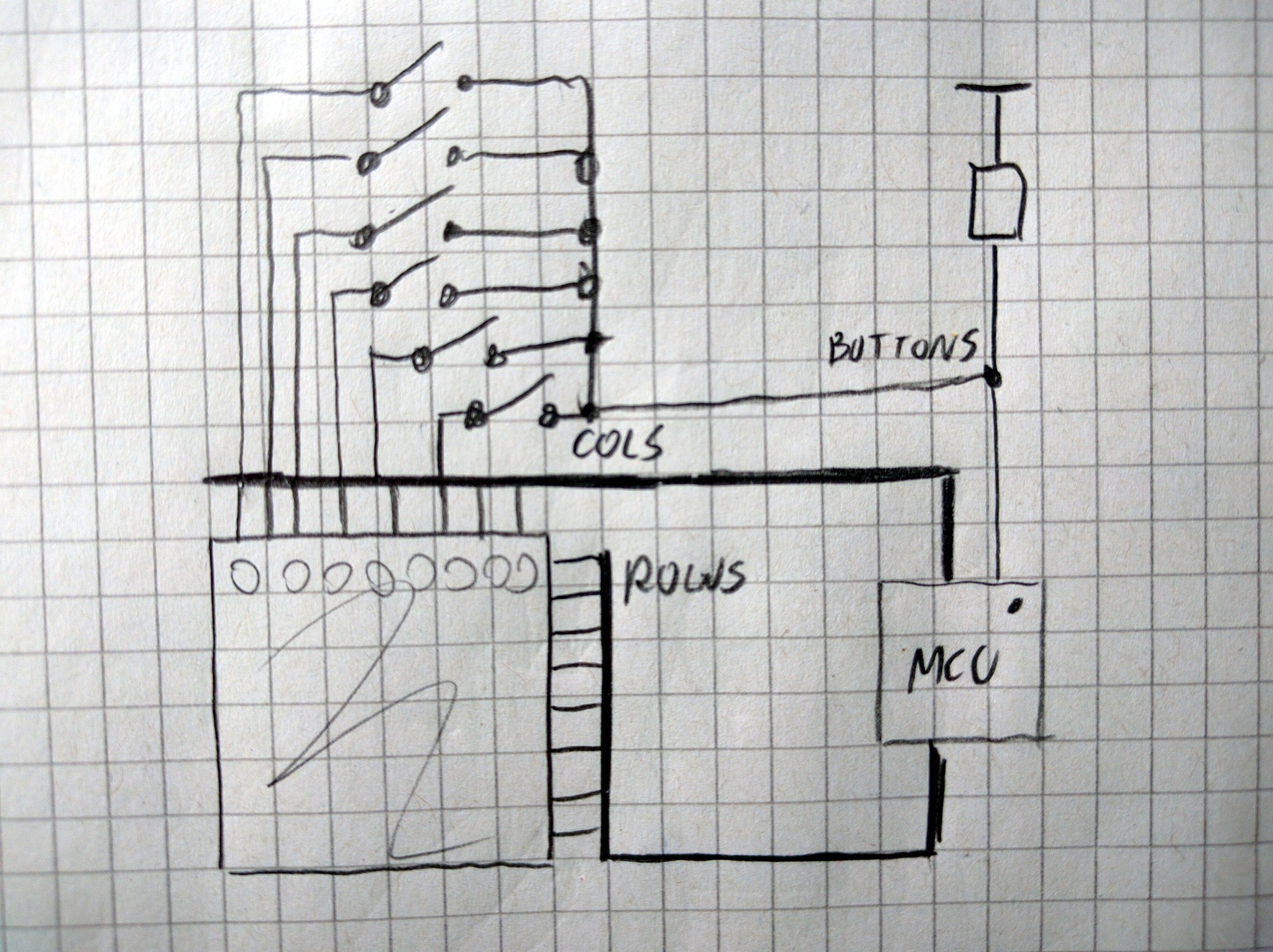
Is there any way I could save pins on the buttons? Right now I use one pin per button, which is kinda wasteful. I could arrange them in a 2×3 matrix, which would require 5 pins, saving me one, but I don't think it's worth it, especially since I would then need additional diodes to avoid ghosting. I could use a resistor ladder and connect all the buttons to an analog pin — but then reading the button state would take longer, as ADC is not as fast as simple digital pins. Can I share the LED matrix pins with the buttons? If I just connected them to the row pins via diodes, I could have an additional fake column for which I would scan the buttons, but that's 6 extra diodes. Hmm, what if the other end of the buttons wasn't connected to GND or VCC, but instead to an additional pin? I already scan the columns, so I could connect the buttons to that, and on every column check the additional pin (with a pullup) for the value of the corresponding button. As a bonus, no extra components and no extra cycles in the matrix scanning, so the brightness shouldn't suffer. That seems like the way to go!
![]()
And that gives me 5 free pins, which together with the 2 debugging pins give me a nice 7 pin header. That should be enough for most basic hobby electronic uses, especially since I can choose pretty much any pins for that, so I can take all the ones that have interesting peripherals on them: ADC, DAC, serial, I2C, SPI, timers.
Now, onto the connector.
I can't just use normal male headers, even though that would make it super-easy to connect the device to a breadboard, because it's supposed to be carried in a pocket, and the pins could lead to injuries, torn clothes and, what's worse, bent pins. I don't want to use an edge connector, like the microbit, because it forces you to buy special hardware and defeats the whole idea of a cheap device. I don't like the big holes for banana plugs/crocodile clips, because who uses banana plugs today? Also they are huge and wasteful. I could use a female pin header — then you could easily use dupont cables to connect it to anything you need. It would even look good next to the matrix display. Or I could just leave the holes for the header unpopulated (which saves me part and some soldering), and use staggered holes, so that you can insert a male pin header when you need it, or solder a female header if you want. I think I will go with that.
The last question is where should the header be located? Obviously we don't want to have it on the same side as the USB plug and power switch. In fact, if this is going to be connected to a breadboard, we don't want an USB plug anymore, and we will need to switch back to a micro USB socket, so that you can have some distance between your computer and the breadboard. But still we don't want them on the same side.
When we put all this together, we get something roughly like this:
![]()
I have ordered enough PCBs this month already, so I will keep thinking about this and maybe adding small improvements.
-
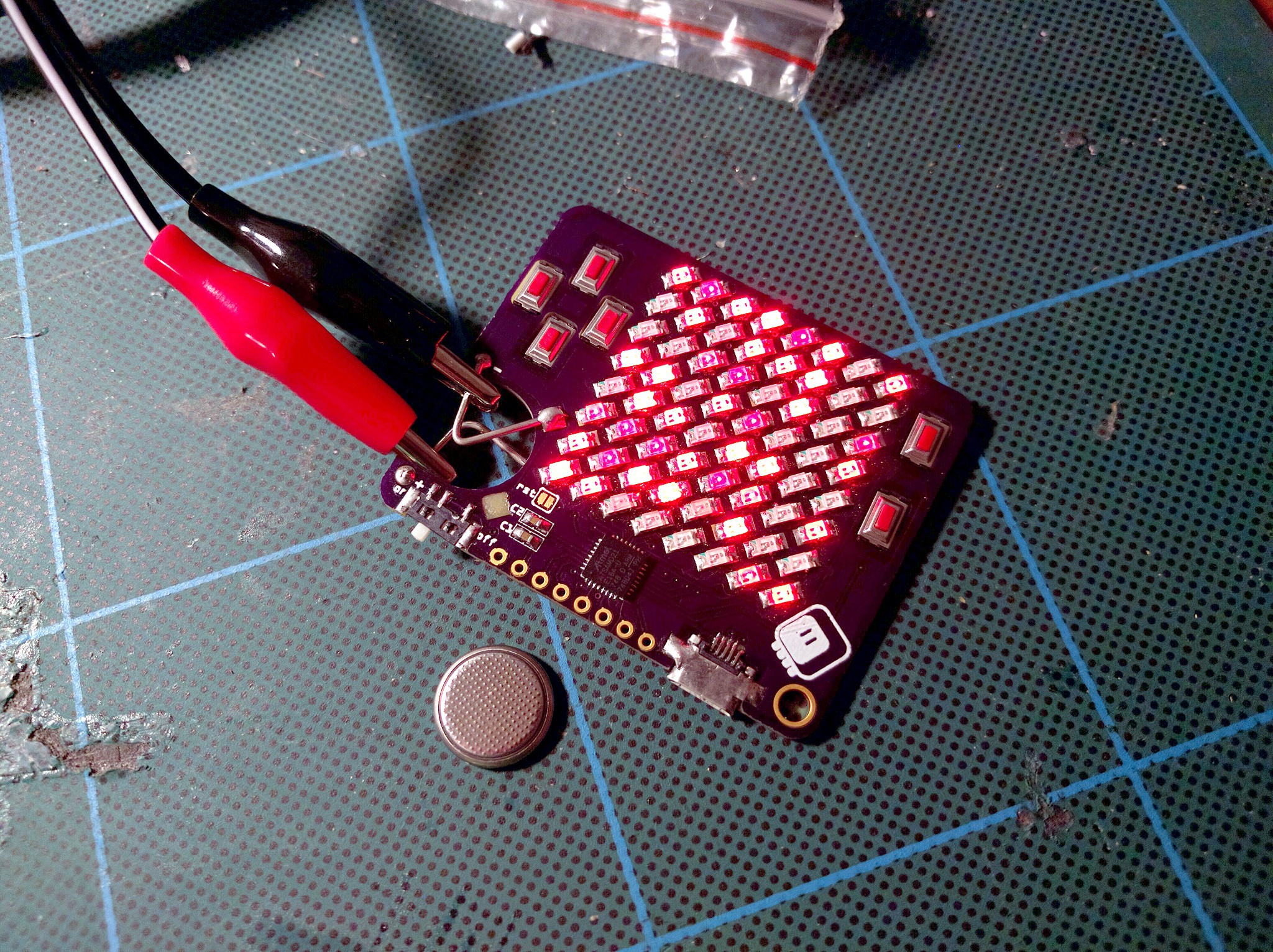
My First Charlieplexed Display
08/12/2018 at 22:18 • 5 commentsOnce I got my matrix-driving code working on the PewPew 8.0, it was just a question of hacking a tri-state gpio pin switching function and some trivial modifications to get it to work with a charlieplexed display. At least it seems so, because it looks like it's working:
![]()
There is a slight problem with brightness — they are way too bright now to distinguish individual shades. Of course my phone camera got overloaded and did something funny with the colors, to the naked eye they are all blindingly red. I will need to tune the PWM somewhat.
I'm powering it with a bench power supply for testing, because the poor little coin cell only lasts a few minutes with the display on at full power — even though the bench supply claims it's only drawing 20mA total.
We will see what I can do with it, but it definitely looks promising.
-
Slowing Down
08/12/2018 at 12:18 • 0 commentsThe flickering problems are solved by slowing down the clock to a reasonable frequency.
What happened?
Well, the clock was running at its 48MHz and generating interrupt requests, but that doesn't mean that the interrupts were being executed at that speed. It takes time to execute them. So they were running as often as possible, back-to-back. Which means that any other interrupt, or anything affecting the speed of execution at all, would affect how often they run, which would be visible as flickering.
The solution? Slow the clock down to a reasonable rate, so that there is plenty of time between the interrupts for executing other things. Like the user python code, for example. Yes, as a side effect, user code can now run.
It was a really basic mistake, I blame the late hour. In any case, it's now fixed and I have the games running.
![]()
As a bonus, since I ended up not using the hardware PWM, I can use the old PCBs, of which I have 20.
-
PWM, Flickering and Timers
08/11/2018 at 22:44 • 0 commentsThe new version of the PCB arrived Friday from @oshpark, and in the evening I started working on it. Assembling was straightforward, with just 4 electronic components. I burned the bootloader, adjusted the board definition to the new pins and flashed the firmware, and the old code works. Next, I changed the rows from DigitalInputOutput objects into PWMOut objects with 100kHz frequency, and instead of setting them low or high when scanning the columns, I'm now instead setting the duty cycle to the desired shade. The code compiled and should work in theory...
![]()
In practice, turns out that setting the duty cycle sometimes takes longer to actually have an effect, and in that time we already switch to the next column (row on the photo, as the matrix is rotated 90°). The effect is a random flickering below every lit pixel.
I also found a bug in CircuitPython, where when you create a lot of PWMOut objects, some of them will share the compare channels, resulting in effectively always having the same brightness. I suspect that when that bug is fixed, I won't be able to create so many channels anymore anyways. So this approach, while it sounded great on paper, is not so promising anymore.
But not everything is lost yet! Today I decided to try and create a separate timer, just for the matrix. I found the code that sets up the timer for PulseOut objects, and pretty much copied it, only skipping connecting the pins to the timer. Unfortunately I had to modify the peripherals library in order to add my function to the interrupt handler — so this is no longer a single clean patch. But lo and behold, it works!
![]()
Pretty good for not having any idea about what I'm doing. Of course at the moment the code is one huge hack, but that's not important, I can clean it up. And believe or not, there are actually 4 recognizable shades on that photo (with a naked eye you can't see the bright spots inside the pixels, and they are all red, not yellow). This also means I will be able to do charlieplexing for that business card.
One problem though — if you look closely, especially on the dimmest-but-not-black pixels, you will see some flickering there. How come? I'm running that timer with prescaler 1, it should run at 48MHz, even dividing that by 8 columns and 6 rendering phases, that's still 1MHz, there is no way you would be able to see that with a naked eye! So what's happening? I really have no idea, but I hope it's something that can be fixed.
I was supposed to be writing a game for Ludum Dare, but instead I worked on this. At least it's also game-related.
-
What are You Sinking About?
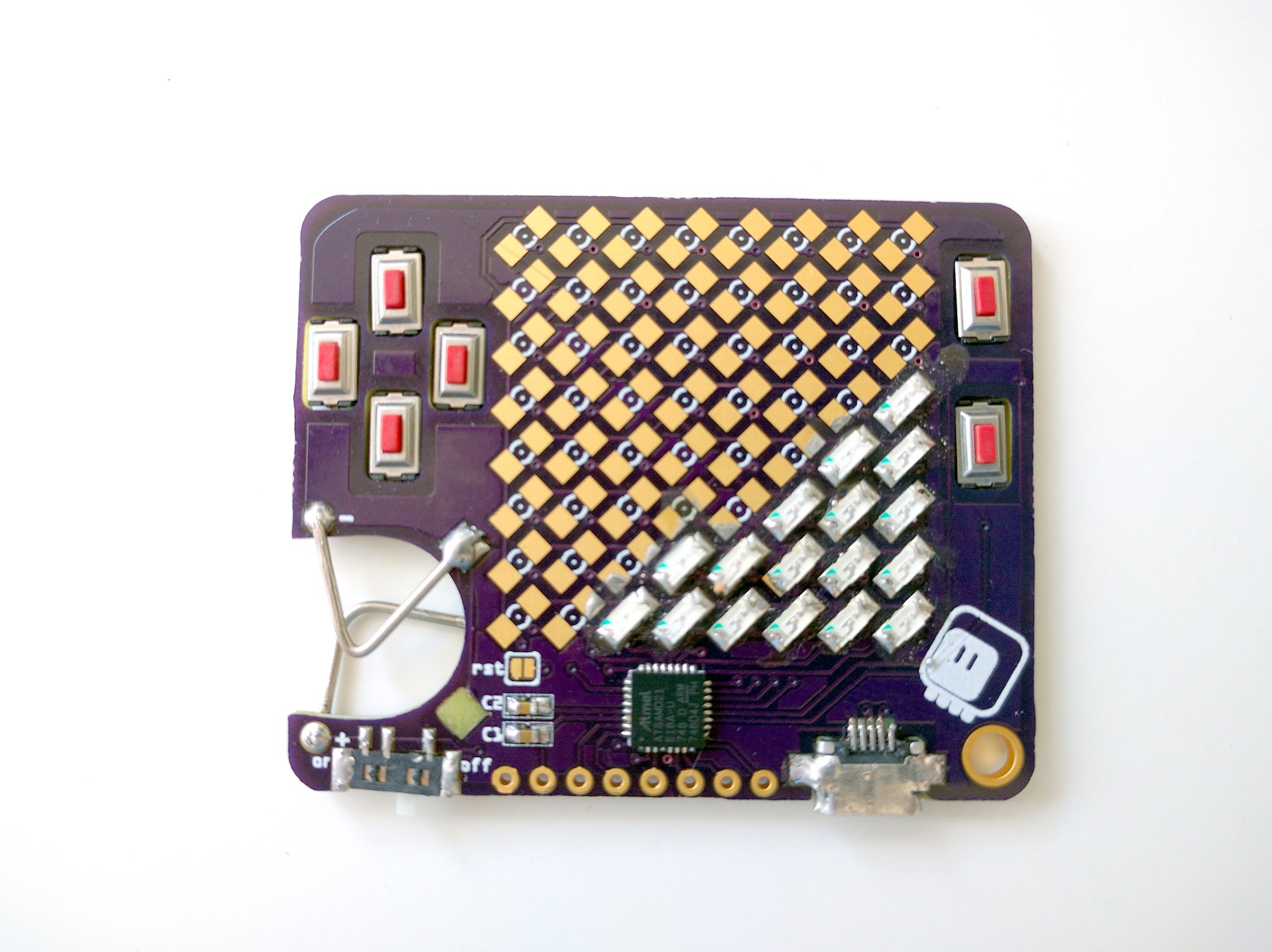
08/10/2018 at 16:31 • 7 commentsToday is the PCB day. A purple envelope arrived, filled with goods. But before I assemble and test the prototype #8 of the device, with all row and column pins capable of PWN, I want to finish an experiment that I described in the first log here. The business card.
![]()
In an attempt to make the device as thin as possible, I decided to try and make most of the component "sunken". What does it mean? It means that the PCB has leaks. I mean holes. And the SMD components that would normally sit on top of the PCB instead go inside those holes, from the bottom, and are soldered to pads adjacent to those holes. Here's a view from the back with the switches soldered:
![]()
And here's the almost-finished device:
![]()
I still need to test the charlieplexing before I solder the rest of the LEDs, but you get the idea.
Of course this is not practical. The holes have to be manually corrected with a dremel (see the first image), because the CNC tool is a bit too big to make good corners (and because I got some sizes wrong). Then the parts need to be fit into the holes just right, and held in place while you solder them. It actually took me several tries to get a working USB socket — you can even see I stripped one of the pads, fortunately that one is unused.
So in conclusion, yes, it is possible to do, no, I wouldn't do it for more than a single unit. It's not practical.
-
Brainstorming
08/06/2018 at 07:52 • 0 commentsIt was a busy weekend, but I did some thinking about the best shape for this little device. If not for the constraints on price and preference to not use cables, I think I would like it to look like this:
![]()
Possibly with some kind of a case on the back, to hide the batteries. But of course that's not possible with the constraints I have, and I have a very hard time placing the USB plug with the horizontal version.
I also found some 6x6cm matrices, so it would be possible to make the same thing, only twice as big. Of course they are quite a bit more expensive, and the PCB would be more expensive, but maybe it would be nice to have a bigger version for the teacher? I even started to design it (it was similar to the one above), but then realized that I should focus, and stopped. The matrix is ordered, though, so maybe later.
PewPew Standalone
A Python-based micro game console, optimized for game development workshops.