- Introduction:
- In photovoltaic systems, solar tracking mechanisms help minimize the angle of incidence (the angle that a ray of light makes with a line perpendicular to the surface of reception) between the incoming light rays and solar panel, which increases the amount of energy that an installation produces. In simple words, solar trackers continuously direct solar panels or modules towards the sun for better energy output.
- Although the invention of a tracking mechanism was a breakthrough in harvesting solar energy more efficiently, the contemporary implementations of solar tracking mechanisms have some significant drawbacks.
- Through this project, I offer an alternative design which is significantly more efficient in terms of power output, durability, production cost and repairability than contemporary models.
- Objective:
- Most contemporary implementations of the solar tracking mechanisms in all solar installations around the world are completely “programmed”. The mechanical solar seeker aims to improve the efficiency of contemporary “programmed” tracking mechanisms by only “electromechanical” means.
- This project also aims to offer a low-cost solar tracking solution so that solar powered systems can be easily installed and maintained in under-developed and developing countries.
- Materials used:
- Light Dependent Resistor (LDR), two solar panels, fours NPN transistors, two reed switches, IC 555 components, assorted resistors, 1000 µF 16 V capacitor, Two BC 557 transistors (PNP), Light Emitting Diodes (LEDs), 12 V DC gear motor, battery power source(9V), one battery clip, two magnets, wooden frame.
- Underlying Principles of Operation and Innovation:
- We first discuss the operation principle of a contemporary programmed solar tracking mechanism and then that of our mechanical version.
- Programmed Solar Tracker :
- On the sunlight reception surface of the programmed tracker, there are a large number of light dependent resistors (LDR) which show variable resistance depending upon the intensity of light falling on each of them.
- The intensities of sunlight received by LDRs on two halves of the sunlight reception surface help in figuring out the position of the source of light. A ratio of intensities of light falling on two halves of the surface is computed as per the resistances shown by the LDRs embedded in both the halves.
- This ratio, computed by an appropriate program, tells the microcontroller to turn the frame (or sunlight reception surface) towards the source of light till the intensities of sunlight on both halves of the surface become equal to each other i.e. the intensity of sunlight falling on the surface becomes uniform which will also be the maximum intensity of the source of light.
- Some drawbacks to be noted about the programmed tracker:
- The programmed tracker “tracks” sunlight at every small instant of time. As soon as the ratio of intensities on the two halves of the surface changes, the microcontroller turns the surface to attain equilibrium. However, this feature of continuous movement is not really necessary because the sun undergoes an extremely small displacement from its position in small instants of time. In such cases, energy lost in moving the surface towards source of light is more than that gained by the tracker. (DRAWBACK 1)
- As the programmed tracker continuously tracks sunlight, a program logic is carried out at all times to compute the relevant intensities. This is the most energy consuming process in the programmed tracking mechanism. Even when the surface is positioned to receive maximum intensity of light, the program logic keeps on consuming energy. (DRAWBACK 2)
- Broadly speaking, we also understand from the above discussion that a solar tracker carries out two basic processes:
- Moving the reception surface (or frame) towards the source of light. This process is termed as “tracking”. (PROCESS 1)
- Stopping when the position of maximum intensity of light (“sun-bright” position) is acquired. (PROCESS 2)
- Keeping in mind PROCESS 1 and PROCESS 2 above, we develop a mechanical tracker to tackle DRAWBACK 1 and DRAWBACK 2 of the programmed tracker as follows.
- Mechanical Solar Tracker:
- Instead of combining tracking and stopping as a single process as in case of programmed tracker, the mechanical tracker carries them out as separate processes. We employ one circuit for continuously moving and oscillating the frame around an axle and another circuit to break the power supply at the “sun-bright” position.
- For oscillation principle, we use an unprogrammed IC 555, magnets, reed switches (to detect the maximum inclination of frame on either side) and H-bridge to switch the polarity of DC gear motor (which moves the frame) at the maximum inclination. This entire arrangement helps in reversal of the direction of motion of the frame from clockwise to anticlockwise and vice-versa without the need of a programmed microcontroller. Hence, we successfully eliminate drawback 2 of programmed trackers. From this point, we will refer to this arrangement as the magnetic proximity circuit.
- As the need of a microcontroller has been removed as per point 2 above, we no longer need to execute a program logic at every instant and hence can use LDRs just to stop the solar tracker at the “sun-bright” position using a simple switching circuit. This circuit successfully implements the stopping process. The switching circuit cuts off power supply depending upon the resistances offered by LDR in high and low intensities of light. LDR shows low resistance in high intensity light and high resistance in low intensity light. Once the power supply is cutoff at the “sun-bright” position, it is only turned back on when the resistance of the LDR increases above a certain threshold i.e. when the sun or source of light gets displaced significantly from its initial position. Thus, we also eliminate drawback 1 of the programmed tracker. From this point we will refer to this circuit as the LDR circuit.
- The above discussion shows the core ideas and principles underlying the design and operation of the mechanical solar tracker.
- Working Methodology:
- LDR circuit:
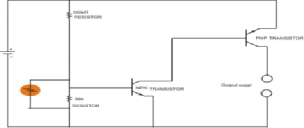
- The LDR circuit consists of a light dependent resistor and a class B amplifier arrangement. The class B amplifier arrangement is just a combination of PNP (positive-negative-positive) and NPN (negative-positive-negative) transistors which are so matched that the PNP transistor is biased (conducts electricity) for half cycle and NPN transistor is biased for the second half cycle of the input. Circuit diagram 1 shows the LDR circuit. The output from the LDR circuit is recorded by IC 555.
- LDR circuit:
Circuit diagram-1
- Let us consider the state of the LDR circuit at the sun-bright position first. At the “sun-bright” position, LDR shows low resistance due to high intensity light falling on it. As a result, the base of the NPN transistor receives high negative voltage as per circuit diagram. This causes the NPN transistor to remain turned off and it does not conduct any current. However, the PNP transistor remains biased and allows the flow of current from it which contributes towards the output supply. This output resets the IC 555 and triggers the DC gear motor to stop. Hence, the reception surface or frame stops at the sun-bright position.
- In case the frame is not in sun-bright position, the LDR shows high resistance due to low intensity light. However, this time NPN transistor gets low positive voltage from the main positive line. As the output from the NPN transistor is turned on, the output from the PNP transistor is cut off and the IC 555 is reset again which triggers the DC gear motor to move the frame till the maximum intensity light is found again.
- Magnetic Proximity Circuit:
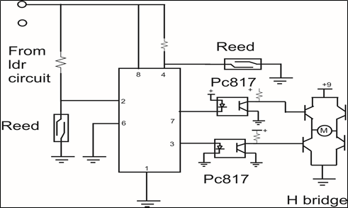
- The magnetic proximity circuit comprises of an IC 555, two reed switches, two magnets attached behind the frame and a H-bridge arrangement. The H-bridge arrangement is a combination of 4 NPN transistors or switches in general that enable a voltage to be applied across a load in opposite direction. It is crucial in switching the polarity of DC gear motor and reversal of the motion of frame. Reed switches are switches which can turn on or off when subjected to a magnetic environment. Circuit Diagram-2 shows the magnetic proximity circuit.
- The magnetic proximity circuit comprises of an IC 555, two reed switches, two magnets attached behind the frame and a H-bridge arrangement. The H-bridge arrangement is a combination of 4 NPN transistors or switches in general that enable a voltage to be applied across a load in opposite direction. It is crucial in switching the polarity of DC gear motor and reversal of the motion of frame. Reed switches are switches which can turn on or off when subjected to a magnetic environment. Circuit Diagram-2 shows the magnetic proximity circuit.
- Circuit Diagram 2
- In the magnetic proximity circuit, the output from the LDR circuit is received by the IC 555. The output from the IC, connected to the DC gear motor via pin number 3 and 7, controls the motion of the frame. Pin number 8 is connected to the positive power supply. Reed switches are connected to pin number 2 and pin number 4.
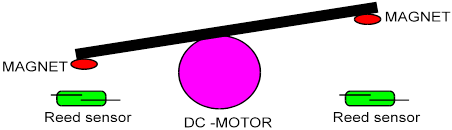
- The oscillation process of the frame is made possible by defining clear bounds for the maximum angle of dip of the frame on either side of the axle of the DC gear motor by using small magnets. At the maximum angle of dip of the frame on either side, the magnets reach sufficiently close to the reed switches to impose a strong magnetic on them. This causes the reed switches to form closed circuits allowing current to flow through them. This change (drop) in resistance offered by the reed switch is recorded by the IC 555 which changes the polarity of DC gear motor. This process can be understood from Block Diagram-1.
- Block Diagram 1
- Changing of the polarity of DC gear motor is established through the H-bridge arrangement. Input of the H-bridge is provided through two opto-coupler circuits which provide optical isolation between IC 555 and H-bridge.
- Advantages over contemporary design:
- Being completely unprogrammed and consisting of no microcontrollers or embedded systems, the mechanical tracker has an extremely low-cost design which make it suitable for implementation in developing and underdeveloped countries to harness solar energy more efficiently. For example, the prototype implementation of the mechanical tracker costs around 25 dollars whereas the prototype implementation of programmed trackers costs around 175 dollars.
- The mechanical solar tracker largely comprises of passive components as compared to active components in case of programmed trackers. As a result, mechanical trackers are extremely durable relative to programmed trackers. For example, if the life of a programmed tracker is 2 years, then the life of a mechanical tracker can be as high as 20 years!
- Since the new design is completely electromechanical, it can be easily repaired by semi-skilled professionals with sufficient knowledge of hardware systems. There is no need for professional programmers to remove bugs from damaged installations.
- The energy output of the contemporary designs is increased by 20 to 22 percent (through experimentation) owing to the absence of a programmed microcontroller and continuous tracking.
- Calculations for an ideal solar tracker :
- We calculate the efficiency of an ideal tracker which means that we assume that the surface of reception (or the frame) gets oriented towards the maximum intensity of light without the expense of any external work. This is done to find the upper bound to the maximum efficiency we can achieve over static solar panels by using solar tracking mechanisms.
- We find this upper bound to be nearly 57%. From online published sources of various companies, the contemporary mechanisms yield an efficiency of around 35 percent over static solar panels. From experimentation, our mechanical tracker is expected to serve an efficiency of 42-43 percent (an efficiency gain of about 20 percent over contemporary designs).