 MasterOfNull
Got off on a tangent trying to make a new feeder using a pin drive.
It sucked, I scrapped it.
So, I stole some things from that design that actually worked, and updated this one.
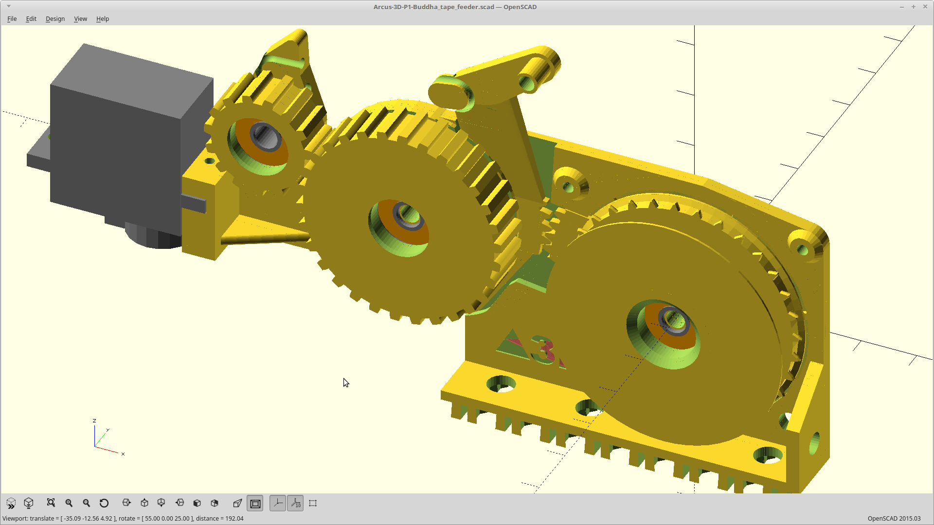
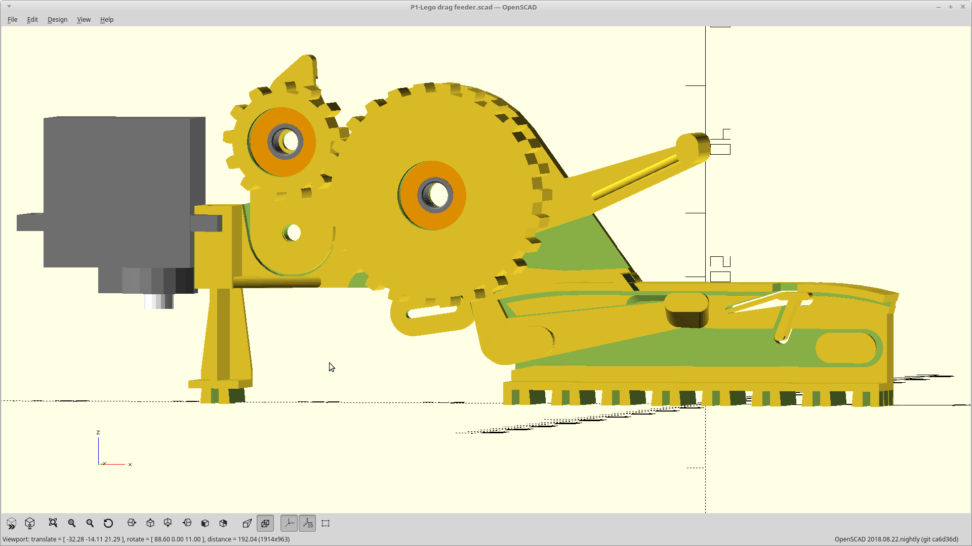
Advances with vertical motion now, both cover tape removal and tape advancement happen on release, and now uses a pinch roller for cover tape removal.
It also uses smaller 4x13x5mm bearings now so the whole thing is smaller and faster to print without giving up maximum part height.
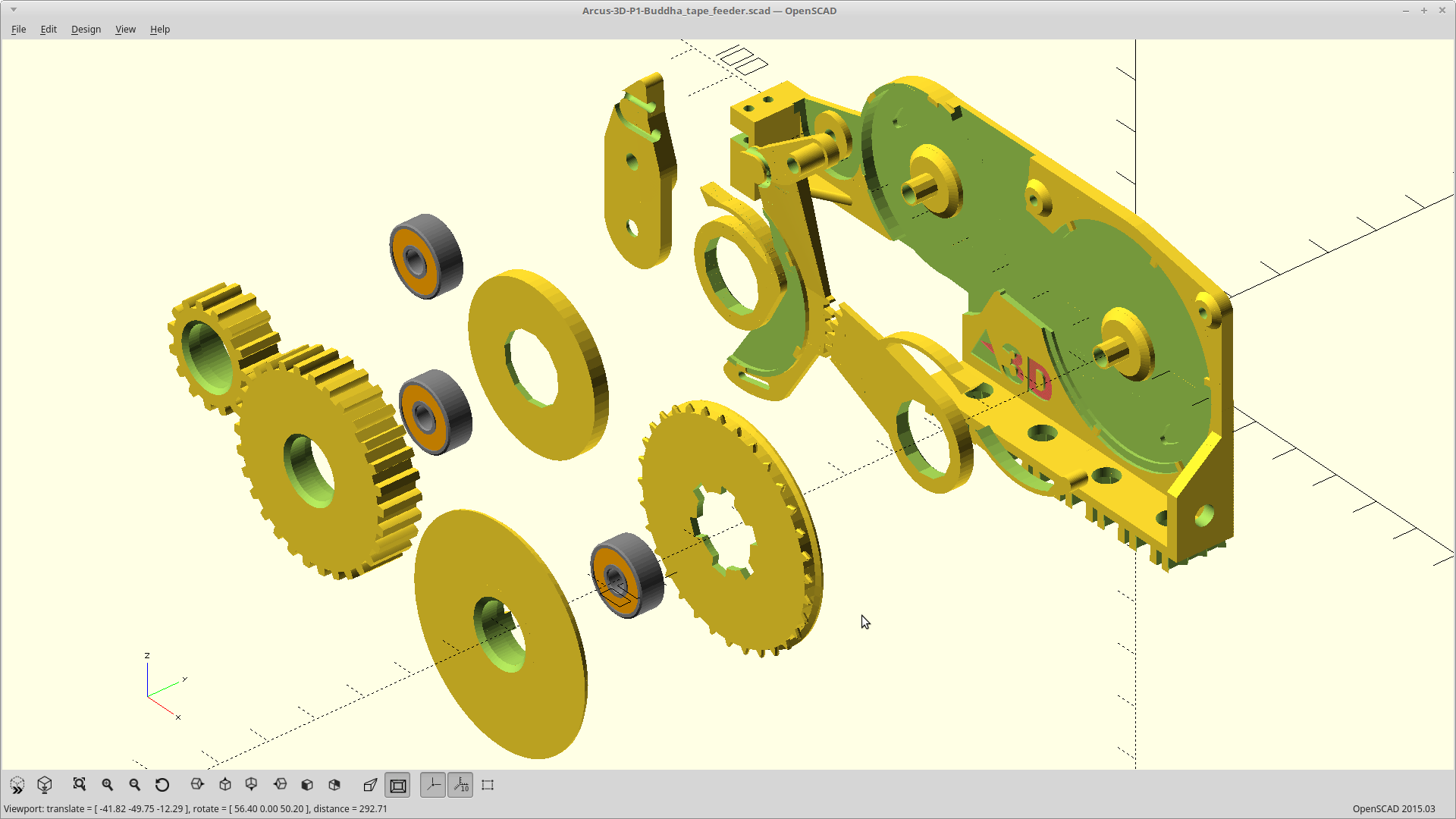
I was also able to ditch the connecting rod in favor of integrated gearing between the drive ratchets, and I switched from a pen spring to using hair bands. The latter will be much easier to adjust the force required for feeding.
Printing.
Discussions
Become a Hackaday.io Member
Create an account to leave a comment. Already have an account? Log In.
Tell me, did you manage to create this version?
Are you sure? yes | no
Good! I'll wait, really want to repeat.
Tell the group how to do the tests.
Thanks for the great solution!
Are you sure? yes | no
Very cool solution!
Are you working on it or is it the final version?
Are you sure? yes | no
The spool version worked more reliably. The issue is both forces acting on the cover gear are pushing the base plate away from it. It bends as a result. I have a plan to add a bar across the bolt area to try to mitigate this, but have not made that part yet.
Are you sure? yes | no