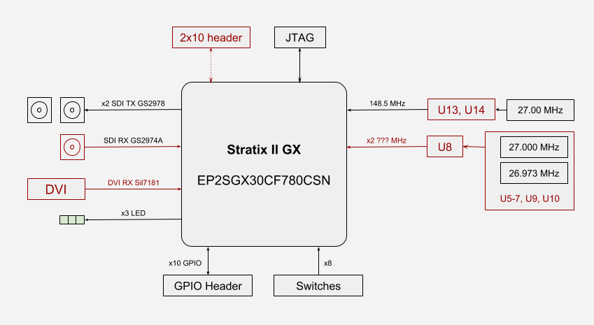
FPGA Device
- Stratix II GX EP2SGX30CF780CSN Device
- 30K Programmable Logic Elements
- M4K RAM blocks (128×36 bits) - 144
- M-RAM blocks (4K×144 bits) - 1
- Transceiver data rate 600 Mbps to 6.375 Gbps
Configuration and Debug
- Serial Configuration Device EPCS16N on FPGA
- JTAG
Expansion I/O
- 2 x SDI TX over GENNUM GS2978
- SDI RX over GENNUM GS2974A
- 10-pin GPIO Header
- 2x10 header
Display
- DVI RX over Sil7181 (no datasheet)
Switches, Buttons, LED, and 7-Segments
- 3 LEDs
- 8 Slide Switches
Power
- 12V DC input
Limitations
- Quartus II Web Edition - 11.0sp1 -- ATTENTION. There is no complete certainty!
- Quartus II Subscription Edition - 13.0sp1
- It is impossible to find documentation on the Sil7181 chip.
Block Diagram

IC list:
U1 GS2974A 4483E3 1052 GENNUM
U2 IDT Q53VH25 7QG Z41104K
U3 EL4511CUZ B1047BF4T
U4 Silicon Image VastLane Sil7181CMHU-0 Q3F619.1-18 1111 AD01KX2
U5 551MLF 1221868 1103
U6 664G03LF 1415966 1112
U7 ZGAH
U8 M 834U 0496
U9 (5-PIN)
U10 (5-PIN)
U11 EP2SGX30CF780CSN
U12 EH11A 109N77
U13 L1BH
U14 527R-01LF 1814763 1114
U15 EPCS16N 9911EV5 PHL101
U16 431 (3-PIN)
U17 6549CBZ V1052TS
U501 EH11A 109N77
U503 GS2978 4371E3 1048 GENNUM
U504 GS2978 4371E3 1048 GENNUM
Pinout

EP2SGX30_sdi_hack.v
module EP2SGX30_sdi_hack (
    input REFCLK0_B13, //148.5 MHz
    output GXBTX_0,
    output GXBTX_1,
    output SD_HD,
    output [2:0] LED,
    input [7:0] SW,
    output [15:0] DEBUG
);
endmodule
EP2SGX30_sdi_hack.qsf
set_location_assignment PIN_J1 -to REFCLK0_B13
set_location_assignment PIN_J2 -to "REFCLK0_B13(n)"

set_location_assignment PIN_E4 -to GXBTX_0
set_location_assignment PIN_E5 -to "GXBTX_0(n)"
set_location_assignment PIN_C4 -to GXBTX_1
set_location_assignment PIN_C5 -to "GXBTX_1(n)"

set_location_assignment PIN_C28 -to DEBUG[0]
set_location_assignment PIN_D28 -to DEBUG[1]
set_location_assignment PIN_D27 -to DEBUG[2]
set_location_assignment PIN_E28 -to DEBUG[3]
set_location_assignment PIN_F28 -to DEBUG[4]
set_location_assignment PIN_F27 -to DEBUG[5]
set_location_assignment PIN_G28 -to DEBUG[6]
set_location_assignment PIN_G27 -to DEBUG[7]
set_location_assignment PIN_H28 -to DEBUG[8]
set_location_assignment PIN_J28 -to DEBUG[9]
set_location_assignment PIN_J27 -to DEBUG[10]
set_location_assignment PIN_K28 -to DEBUG[11]
set_location_assignment PIN_K27 -to DEBUG[12]
set_location_assignment PIN_L28 -to DEBUG[13]
set_location_assignment PIN_M28 -to DEBUG[14]
set_location_assignment PIN_M27 -to DEBUG[15]

set_location_assignment PIN_B10 -to SW[0]
set_location_assignment PIN_A10 -to SW[1]
set_location_assignment PIN_C8 -to SW[2]
set_location_assignment PIN_A9 -to SW[3]
set_location_assignment PIN_B8 -to SW[4]
set_location_assignment PIN_A12 -to SW[5]
set_location_assignment PIN_A7 -to SW[6]
set_location_assignment PIN_A8 -to SW[7]

set_location_assignment PIN_AB9 -to LED[0]
set_location_assignment PIN_AC9 -to LED[1]
set_location_assignment PIN_AD10 -to LED[2]

set_location_assignment PIN_AH7 -to SD_HD
Pulse and Square wave Generator.
Discussions
Become a Hackaday.io Member
Create an account to leave a comment. Already have an account? Log In.