 Maximiliano Rojas
For a better comprehension of the design and development aspects, I'll present a series of haptic systems that serve as inspiration for this work, besides a little of mathematical and electronics background will be mentioned for a better understanding. It's mandatory to present the names of the programs that I used or will use for this project as the code implemented in the microcontroller that can be used as examples for who want to deepen on this topics, or inclusive in the same project, in a more guided way, now, without any further ado:
1 Mathematical background
In this sections, the Denavit-Hartenberg parameters and the homogeneous matrix will be explained, especially in what extraction of data refers.
1.1 Denavit-Hartenberg parameters
The Denavit-Hartenberg parameters are very useful to describe, in a systematical way, the kinematic structure of a serial robot, the method consists in finding a series of relations between two frames (or vectorial spaces to be more precise) in such a way that, through a special kind of matrix, appears a linear transformation that allows us to convert vectors of one frame to another of reference. This makes easier to found, for example, the position and orientation of the end effector of some robotic arm taking the base of this (or any other point of interest) as our frame of reference. The parameters are:
 *Extracted from Peter Corke-Robotics, Vision and Control. Fundamental Algorithms In MATLAB book, I really recommend this book in case if you want to deepen.
1.2 homogeneous matrix
This matrix is a way to represent a linear transformation between two frames in such a way that the orientation and position of a spot are defined in one frame of reference (j) with respect to another (j-1), its structure is defined through the Denavit-Gartenberg parameters and is:

In a general way, with Denavit-Hartenberg parameters, is:
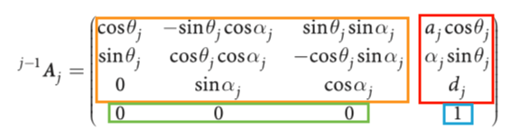
Where the sub-matrix are:
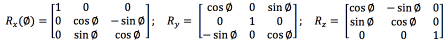
- Rotation matrix: This sub-matrix associate the rotation of one frame and returns its equivalent with respect another frame (like the orientation of the end effector of a robotic arm with respect to the base of this robot) and you can extract the roll, pitch and yaw angles from the relations of its components. It has three canonical forms that correspond to the rotation in the three main axes (x, y, z), those are:
- Translation matrix: The components of this matrix represent the x, y, and z of a point in a 3D space after to apply the linear transformation, there is no any standard or canonical form because its depend on the structure of the robot and the joint considered.
- Perspective matrix: Through this sub-matrix, you can transform the perspective of a frame through projections managed for its components, no perspective modifications correspond to [ 0 0 0 ] vector.
- Scaling matrix: Through this sub-matrix, you can scale the dimensions of the frames of interest, the normal dimensions are given by the vector [ 1 ].
2 Digital filters
In case that the sensor used returns a series of samples with no desires high-frequency components, you can design a low-pass filter that "softens" the curve of the signal that is processing in such a way that no exist any abrupt change in the systems that used this data as input, for example a filtered signal is:
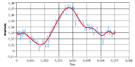
red - filtered signal blue - normal signal
To solve this problem we may consider using analog filters (like an RC circuit), but this present two big problems, first, electronics components has error margins in their values not only by its production (like the tolerance in resistors) but for external or physical problems too (like overheating), and second, if the order of the filter is too high it can be very expensive to build. So, for solve this we will use IIR filters.
IIR filters (infinite impulse response) are those that the output of a processed signal depends on a determinate number of samples scaling by coefficients, where is there the challenge of the design, found the proper coefficients for the desired response, the mathematical form of this is:
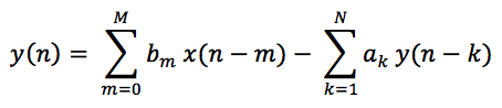
As you can see, the output signal y(n) depends on both inputs (actual an already used) and outputs already processed, then, depending on the order N of the filter, the coefficients to determine are:
- M + 1 coefficients "bm" of the input.
- N coefficients "ak" of the output already processed.
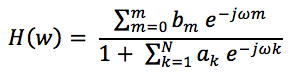
Once we have the coefficients, the frequency response can be obtained by:
Nevertheless, thanks to the algorithms implemented in Matlab, the digital aspects can be analyzed and then, through a faster analog filter design, generate the digital filter, we can convert analog filters into digital ones with only a command, but its imperative to consider that the relations between the sampling frequency and the digital equivalent of the analog frequency don't break the "sampling theorem".
*sampling theorem consists in that our sampling frequency must be bigger than the double of the highest frequency contained in our analog signal.
It may happen that our sampling frequency change due to externals perturbations, for example, for overheating or algorithm that change its time of operation, to fix that we can implement a first-order IIR filter because exist a systematic way to have the coefficients, and this method can be implemented in a microcontroller with a timer, but I don't think that this will be necessary, however I mention it in case of this be of some utility for someone.
3 Haptics devices
In this section will be presented and analyzed briefly some haptics devices that serve as inspiration for this work with a special interest in those characteristics that can be replied through some sort of visual inverse engineering by means of images and videos available in the developers official pages.
3.1 Touch
This haptics device was development by 3D-SYSTEMS company and its principal features are to be compact and portable, it can measure 6 degrees of freedom, three for position and three for orientation, besides it has a three degree of freedom force feedback (for the position). Its end effector can be removed and replace with another provided by the company, like a pen with two buttons.
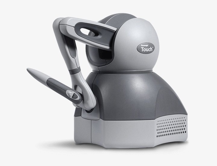
This structure is quite interesting because of its look like a standard six degree of freedom robotic arm, surely had three degrees of freedom concentrate in the base and through a pulley, it can measure the elbow angle.
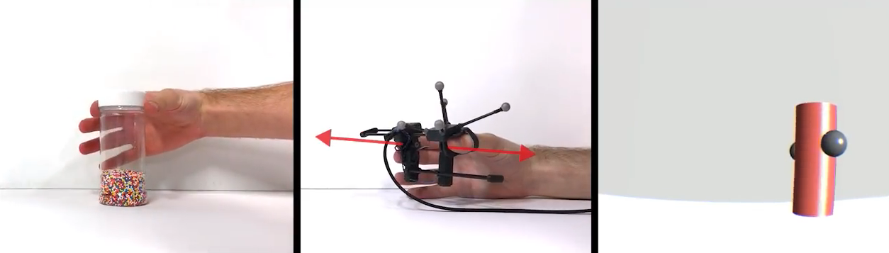
3.2 Gravity
This haptic interface developed by Stanford University to simulate weight and grip of a virtual object. It has four degrees of freedom feedback, three for inertia sensation and one for grip. In this case, the way that this device holds a determinate position is interesting, the design of the break looks tiny but efficient, I think that this can be replied in a more cheaper an simpler way, but probably bigger.
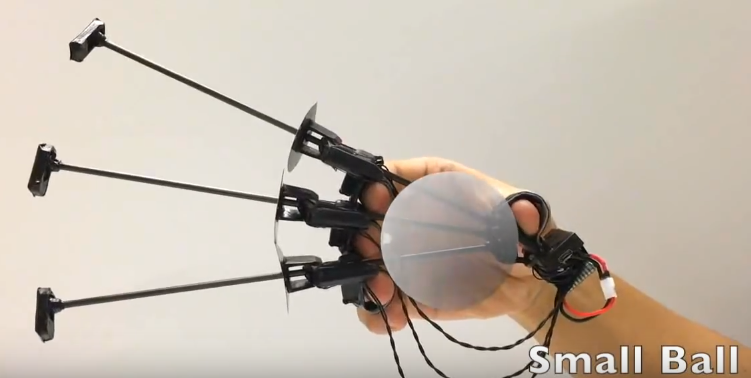
3.3 Wolverine
This is another haptic device developed by Stanford University specially designed to grasp virtual objects, is like the tiny version of Wolverine, but for each finger! It can measure the orientation of the hand and position of each finger, those little parts with the circle are brake so if I can reduce the volume of the replies of Wolverine's brake, I will try to reply this one.
4 Programs
These are the programs that I use or will use for the design, test and validate all:
- Arduino - coding
- MatLab - coding and simulation
- Fusion 360 - CAD desing
- PSIM - Circuit design
- Unity - VR applications
5 Bibliography
If you want to go deepen on this topics I strongly recommend these list of books:
- Fundamentals of electronics circuits - Alexander Sadiku (basic circuit theory).
- Introducción al procesamiento digital de señales - Juan Vignolo (digital signal processing, sorry it is in Spanish, but is a very good book) .
- Vision and Control. Fundamental Algorithms In MATLAB - Peter Corke.
- Robot Analysis: the mechanics of serial and parallel manipulators - Lung-Wen Tsai.
- Fundamentals of Robotic Mechanical Systems: Theory, methods and Algorithms - Jorge Angeles (very heavy in its mathematics).
Discussions
Become a Hackaday.io Member
Create an account to leave a comment. Already have an account? Log In.