 Blair Vidakovich
This is half the Flip-Flop completed. It is the entire right side of the R201 specification. It now includes that actual Flip-Flop, and the 3 edge-triggered inputs on the right hand side of the design, including the voltage divider.
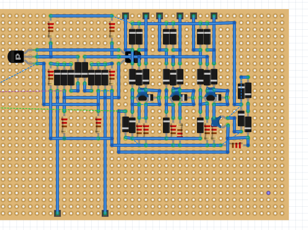
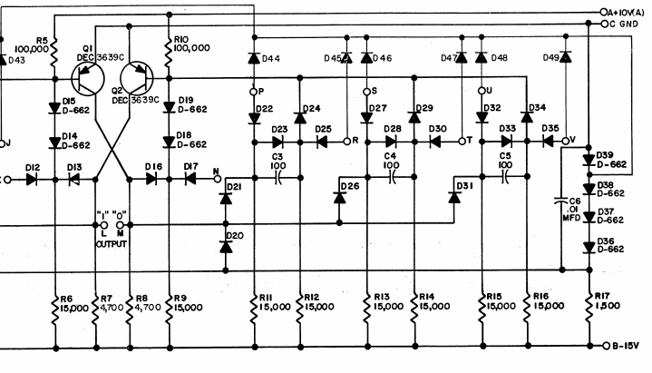
This layout corresponds to this fraction of the R201 schematic:
Discussions
Become a Hackaday.io Member
Create an account to leave a comment. Already have an account? Log In.