 Blair Vidakovich
I will be using the Free Software program Qucs to plan out the electronics of the RAVEN.
The digital electronics of this computer will be based on the R-Series logic of the DEC PDP-8/S.
I started planning out the registers of the RAVEN, following this 'cookbook' suggestion inside the 1967 DEC Logic Handbook:

The DIRECT SET lines will not be tied together, and they will not be unbuffered. The DIRECT SET lines will have a three state input implemented with an extra R-Series Diode-Capacitor-Diode Gate attached to each separated DIRECT SET line:
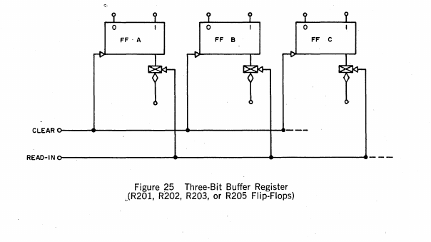
So the extra 'CLEAR MDR' control signal will be implemented by attaching all DIRECT CLEAR lines together. This will be useful for the CLEAR STACK CELL control signal/sequence.
Flip-Flops Required for Registers
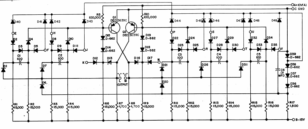
This is a 5-input single Flip-Flop as specified by DEC Flip-Chip code R201:
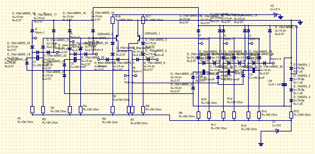
And this is the corresponding circuit schematic in Qucs:
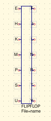
And this is the sub-circuit schematic that is generated by attaching ports to the appropriate inputs and outputs:
Now the registers can be designed (and hopefully simulated) in Qucs and an accurate Bill of Materials can be generated.
Discussions
Become a Hackaday.io Member
Create an account to leave a comment. Already have an account? Log In.