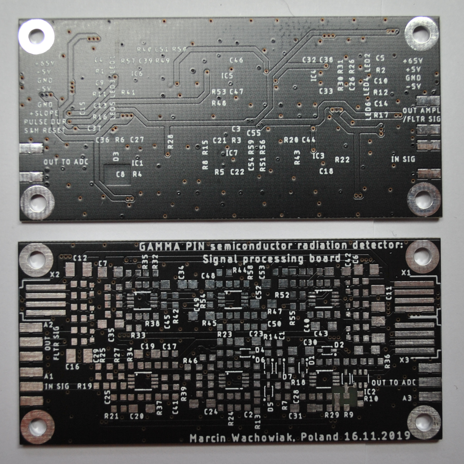
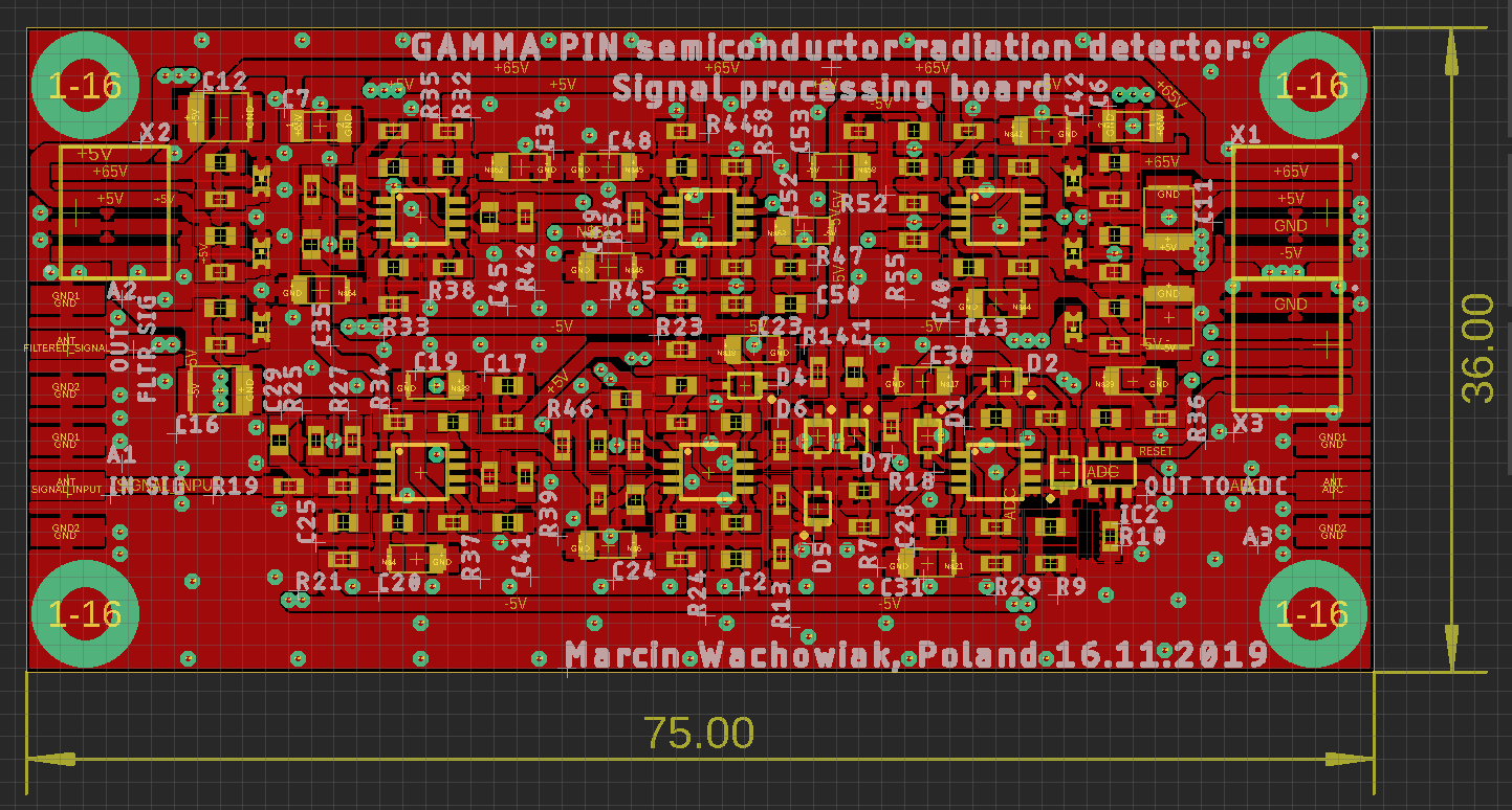
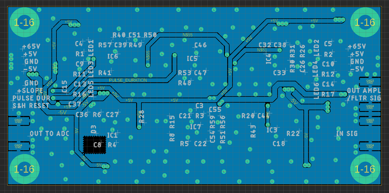
Recently I have finished and produced the third version of the detector. Several improvements have been made considering the issues with the previous versions. All files including gerbers, schematics, boards and latest simulation can be found on my GitHub repository. Change log:
- The whole circuitry has been split into two separate boards named accordingly to their function: preamplifier and signal processing. This helped to organize the components properly and extract less sensitive components outside of the detector chamber which is a crude metal box. Separating fast switching comparators from the charge sensitive parts is also an additional advantage. All signals are handled through SMA interface to ensure minimal external interferences.
- Preamplifier segment required additional amplifier to boost the signal levels, before sending them to the processing boards. LTC6228 was added to handle this. Due to the fact that the design uses double amplifiers in a single package I had one additional amplifier left on the signal processing board which was used to increase the order of the low pass filter.
- The bootstrapping transistor BF862 was replaced with CPH3910 as the BF recommended by a design note (https://www.analog.com/media/en/reference-design-documentation/design-notes/dn399f.pdf) has been declared end of life. You can still come across the BF in shops as retailers have some reserves. Performed simulations show that there is no substantial difference in the performance. Probably the noise figures are a little bit greater. You can view the results in the discussion below this log.
- Signal processing board is equipped with “Filtered Signal” SMA output that can be used to connect the detector to a high-speed ADC or Multi Channel Analyzer for farther evaluation. This output is preceded by three stage low pass amplifier that can be altered to serve as normal amplifier without bandwidth limitation or any shaping effects.
- Signal processing board and preamplifier are now populated with many bypass capacitors as recommended in the application notes. There is also an additional power connector on the signal processing board which is intended to forward the power to the preamplifier to avoid mess of split cables.
- Preamplifier is now compatible with both VBPW34S and TEMD5010X01. There is additional milled line that should enable easy snapping or cutting of the board if you intend to use it with a single diode.
- Around the charge sensitive path, a guard ring was introduced to minimize current leaks. Exposed and tinned trace is connected to the voltage similar to the input of the TIA. Although it is not powered by buffer following the voltages on the trace it may improve the performance a little bit.
- At the bottom of the preamplifier an exposed pad was placed to provide grounding for metal screening of the diodes. You may simply solder the screen to mass without scraping the solder mask.
- Molex pico-spox horizontal connectors (87438-04) have been replaced with vertical ones (87437-0443), as the horizontal ones are no longer recommended for projects. The vertical orientation helps to insert the plug and the cable can be easily bend to minimize the space taken up by the detector.


Discussions
Become a Hackaday.io Member
Create an account to leave a comment. Already have an account? Log In.
You've also moved from the discontinued BF862 to the CPH3910. I'm interested to know how well they compare.
Are you sure? yes | no
It is hard to tell whether there are any significant differences. I couldn't observe it with measurements of the assembled detector as there is no clear reference or calibrated source. So, I performed a simulation with both CPH3910 and BF862. Only the transistors were replaced, the rest of the circuit remained unchanged. There is no noticeable difference in the results. Perhaps in noise figures. Nevertheless, both transistors perform quite well and CPH3910 seems to be a reliable equivalent of BF862. Some differences may occur over a wider spectrum of energies - (currents) maybe then the results would vary more.
Here are the screens from the simulations showing the plots. CPH is on the left and BF on the right:
https://imgur.com/a/BnLvWXK
Are you sure? yes | no