The early stage prototype of the detector was designed to have an array of about 50 PIN diodes.
To distribute them equally I divided the array into 7 rows with 7 diodes each. Every single row had
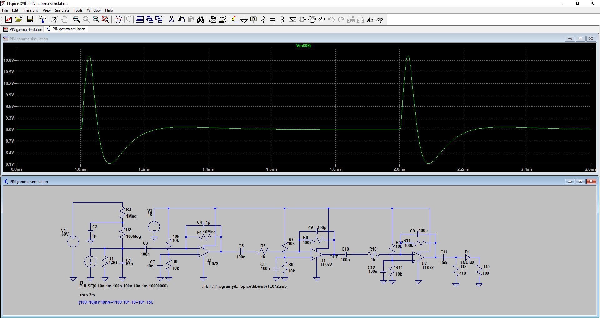
it’s own sensing amplifier construced using TL072. This common and easily accesible solution was supposed to give me an insight to futher work with this kind of detectors. The design was preceded with simulations in LTspice to check what results may I expect.
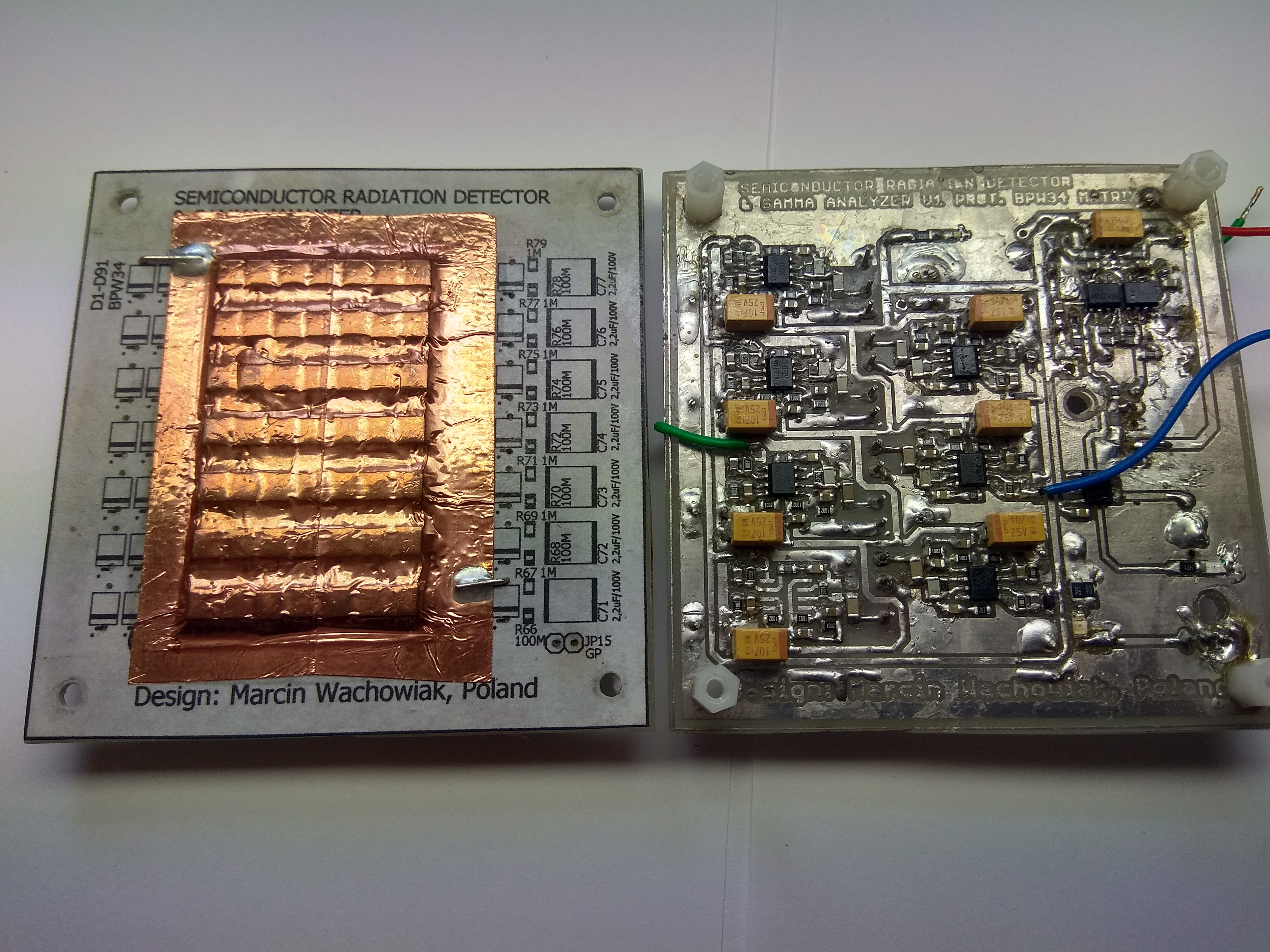
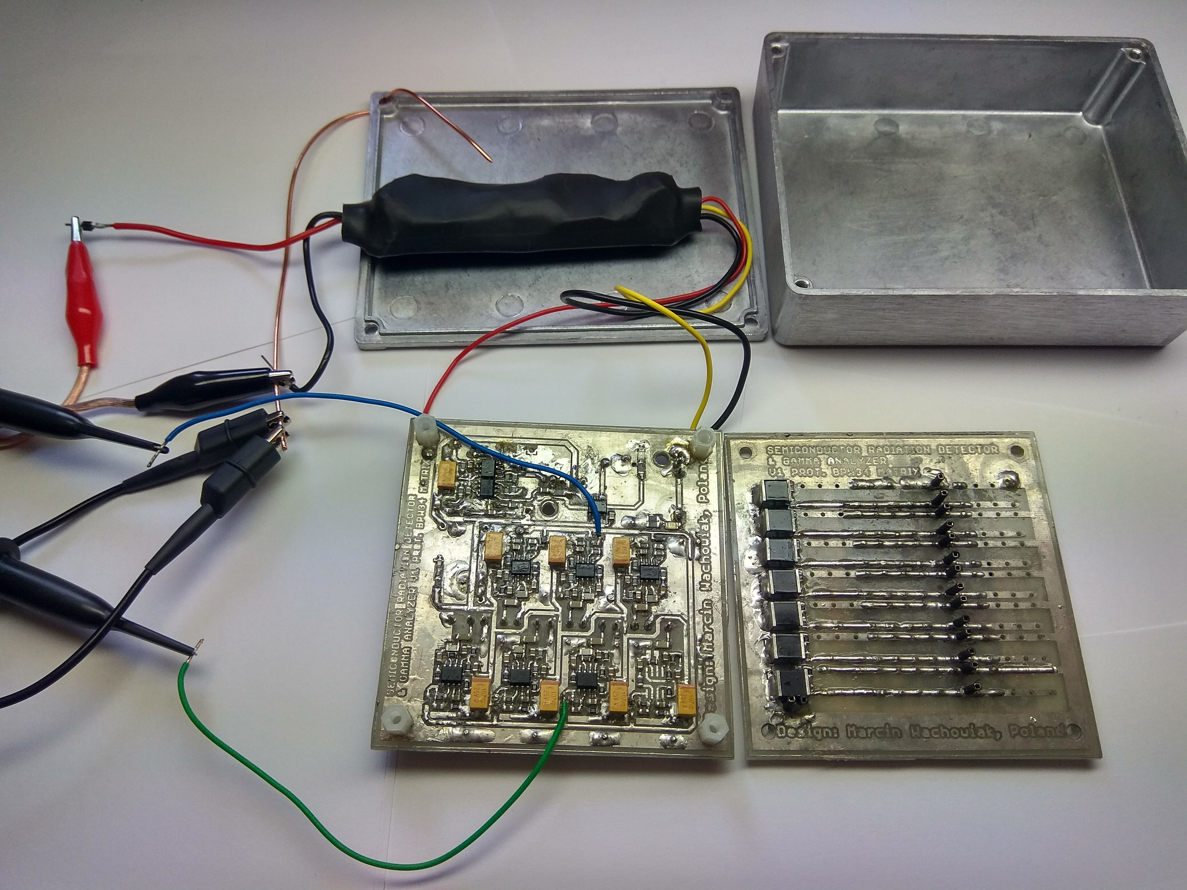
This prototype was created in a wafer fashion to make it smaller and stackable. The power supply was based on common step-up inverters using LM2577. By changing the feedback resistor they may work up to 65V. TL072 worked at 18V and diodes were biased by 60V. These power modules were shielded to reduce the noise emitted by the coils.
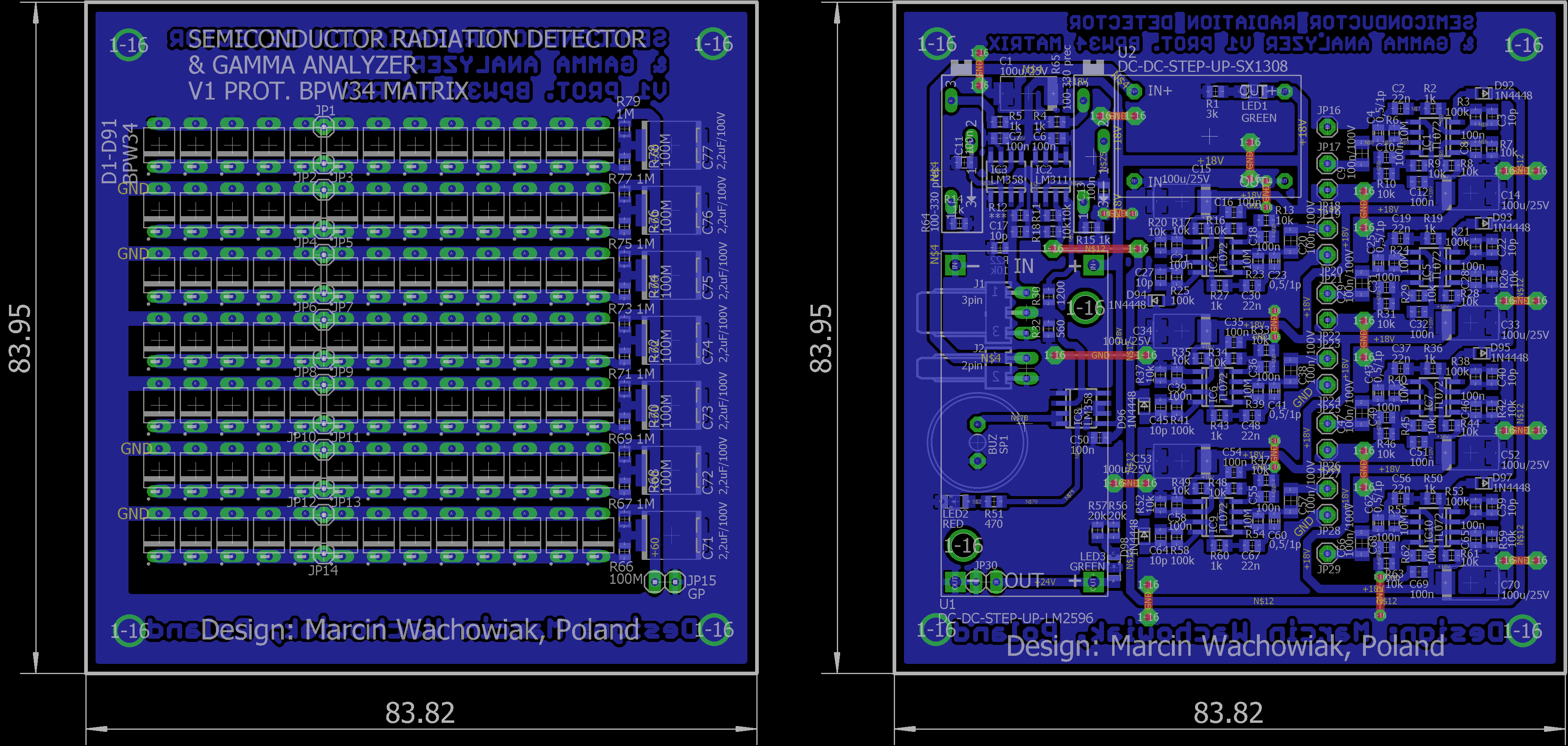
Unfortunatelly, in the final stage of the signal processing there have occurred an error stopping the grid detector from functioning properly. The pulse signal is negative and in the circuit there is diode added at the output of the TL072. It was supposed to prevent the signals from mixing if they were positive. This awful mistake is still present in the PCB files. If you wish to test your own detector make sure you have replaced the diodes with a proper solution that would stop the signals from interfering.
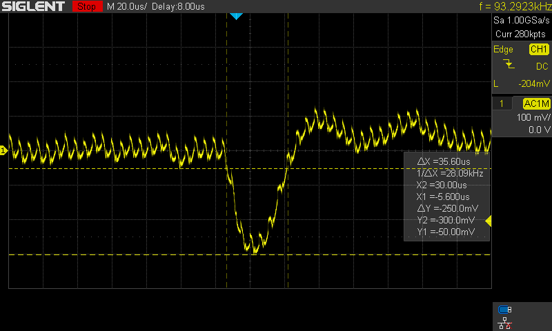
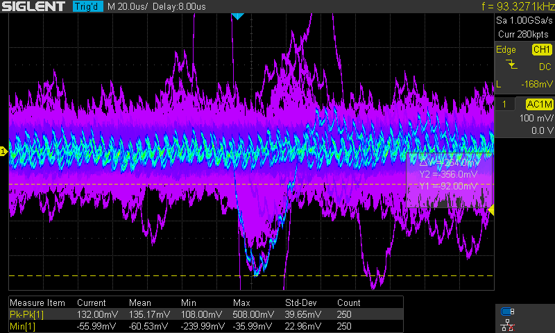
I still managed to get use of the single row to measure some radiation. The first measurment was without any source. Even the background radiation managed to leave a trace, although the pulses were significantly smaller and happened less often.
Then I placed a thoron mantle at the sensing area. Simultaneously the pulses were higher and more frequent. For a single singal trigger I didn’t have to wait even a second.
On the whole, this prototype has allowed me to focus on a few problems that will need to be solved:
- Noise and parasitic capacitance should be kept as low as possible. The whole instrument for proper working conditions, will have to be enclosed in a grounded metal chasis.
- The power supply circuits will need to be with reduced EMI and voltage ripple. This induces
me to use charge pump voltage regulators, which should be suitable for the job. - For any future applications the single row detector should be made modular and portable to enable easy use. The sensor will be in a shape of a thin stripe with a connector at the edge.
The early design was quite a crude one. The second one is going to be well thought over to provide reliable results.
Discussions
Become a Hackaday.io Member
Create an account to leave a comment. Already have an account? Log In.