 Arduino Enigma
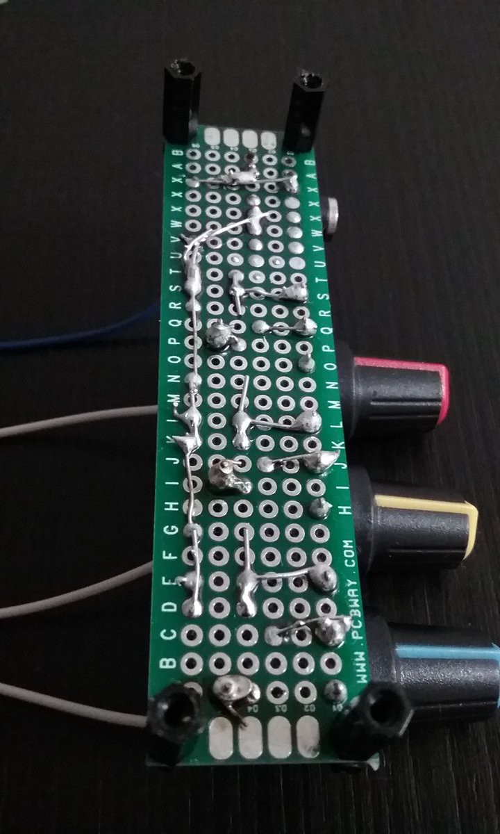
Here is a picture of the assembled mixer:
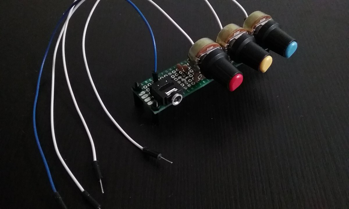
The white wires are signal inputs for each different channel. The blue wire goes to the common
ground. This mixer assumes all channels share a common ground.
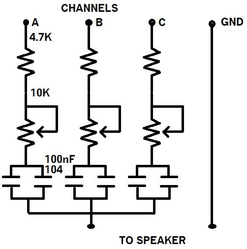
The component values were chosen based on what I had lying around.
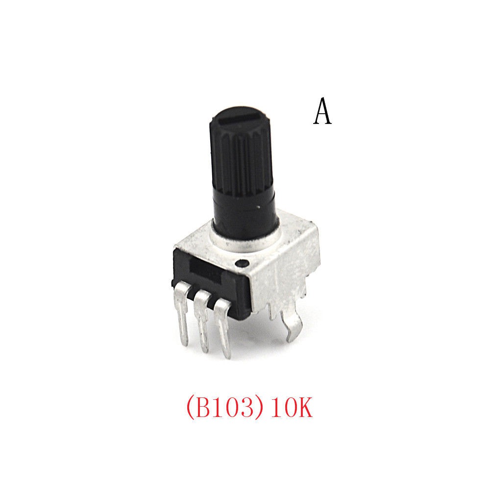
Currently waiting for the a shipment of the following potentiometers in order to populate the voice cards.
Discussions
Become a Hackaday.io Member
Create an account to leave a comment. Already have an account? Log In.