 TM
TM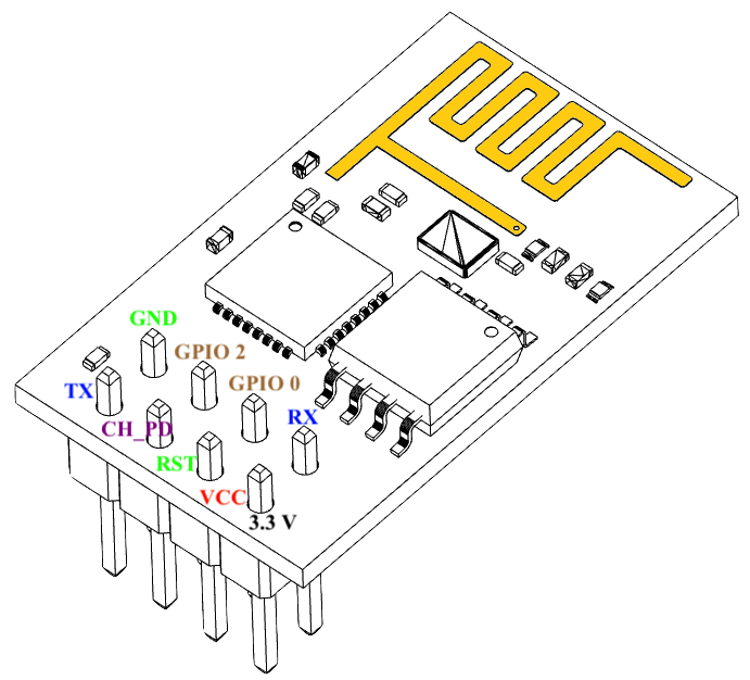
(ESP-01 diagram from Wikipedia.)
ESP-01 connections:
| ESP-01 Pin | Connects to: |
|---|---|
| VCC | +3.3V supply |
| RST | Reset Dupont lead |
| CH_PD | +3.3V via 10kOhm pull-up resistor |
| TX | "FTDI" Adapter RXD |
| RX | "FTDI" Adapter TXD |
| GPIO-0 | GPIO-0 Dupont lead |
| GPIO-2 | Neopixel Data Input |
| GND | Power supply ground |
"FTDI" USB Serial Adapter connections:
| "FTDI" Adapter Pin | Connects to: |
|---|---|
| GND | Power supply ground |
| TXD | ESP-01 RX |
| RXD | ESP-01 TX |
Neopixel Ring Connections
| Neopixel Ring Pin | Connects to: |
|---|---|
| GND | Power supply ground |
| Power | +5V Power supply |
| Data Input | ESP-01 GPIO-2 |
You'll need a power supply that can deliver +5V (for the Neopixels) and +3.3V (for the ESP-01). I've been waiting for over a month for a delivery of AMS1117 5V to 3.3V step-down converters, in the meantime, I'm using a +5V supply connected to an NTE1904 LDO voltage regulator circuit.
To program the esp8266, connect the GPIO-0 Dupont lead to the common ground and then touch the Reset Dupont cable to ground to boot the module. Because GPIO-0 is grounded, the module will boot into programming mode. You can now press the upload button on the Arduino IDE at your leisure. When programming is complete, the module should reset itself and run the program (even though GPIO-0 is still pulled low). Disconnect GPIO-0 from ground before manually booting or resetting, or you'll end up in programming mode again.
Discussions
Become a Hackaday.io Member
Create an account to leave a comment. Already have an account? Log In.