Close
0%
0%

Puff-Suck interface for fast text input

A tube connected to a bipolar pressure switch drives an Arduino which translates puffing and sucking into Morse code and then into text.

anaAna
Public Chat
Similar projects worth following
A tube connected to a custom made bipolar pressure switch drives an Arduino which translates puffing and sucking into Morse code and then into text.
Puffs make repeating short pulses (dots) and sucks repeating longer pulses (dashes) just like ham radio amateurs do with a dual-lever paddle.

Puff-Suck (or Sip and Puff) systems are one of the ways used by people with little or no arms mobility to communicate or interact with computers. (Voice control is a non-ideal computer interface except in some controlled environments.)

A screen displaying a keyboard allows the user to move a cursor (using some kind of joystick, buttons or even eye tracking) to a desired letter and then puff/suck to select it. Move again to the next letter, puff/suck again.  Again and again.

"There has to be a better way!" we thought.

And we found one. 

A Puff-Suck system has three states:

  • Puffing
  • Sucking
  • Neither

Since Cat has had some experience with Morse code, he thought "Huh, a dual-lever paddle has three states... so you could signal Morse code with a Puff-Suck system."

You may be thinking... well, you need to learn Morse code.

Morse code is not very difficult or time-consuming to learn, and the time saved by using this device accumulates to much more than the time that is takes to learn Morse code

With a dual-lever paddle, one lever is used for "dots" or "dits", while the other is used for "dashes" or "dahs". If you continue to hold the dot lever, it will keep sending dots until you release it, and same for dashes.

And thus, the idea for our Puff-Suck interface was born.

If you would like to see a working version in use, head over to this project log!

NOTE: The times that logs, code, and other resources may be strange since we signed up for Hackaday after beginning this project

  • 1 × Arduino Almost any will do (for now)
  • 2 × Film Canister Caps Or similar
  • 2 × Infrared LEDs We took ours from QRD1114s
  • 2 × Opto-Transistors We took ours from QRD1114s
  • 2 × 33K Ohm resistors This value may change depending on what components you use

View all 9 components

  • Video of working prototype!

    Ana08/20/2018 at 15:36 0 comments

    As bespoken, we took the video to show our working Puff-Suck!

    It still has some kinks to iron out (as does my Morse code, this was not the first take) and more software functionality, but this is a huge step in the right direction.

    Until next time,

    Ana

  • Updates

    Ana08/16/2018 at 20:03 0 comments

    After a few head-scratching hardware bugs, we finally connected the puff-suck switch to the Arduino Mega 2560 and got our first prototype working. Video coming soon!

    Aaand we have another todo list:

    • Clean up and comment code (in progress)
    • Connect interface to a Leonardo so we can control the mouse and keyboard
    • Implement more codes and escape sequences, perhaps custom codes

    Until next time (when hopefully we will have a video and more to show you),

    -Ana

  • The difference between our project and the TandemMaster

    Ana08/09/2018 at 17:17 0 comments

    In the last project log, we briefly mentioned that we found an existing product that is similar to ours.  

    We had searched before we started our project and didn't find anything like it.  But searching for our own project from another computer, brought it up when we misspelled some term.  Searching for morse puff auck interface brought up this "Morse Codes for Computer Access" page.

    Let's have a look at the differences between our project and the TandemMaster.

    We've never seen a TandemMaster but from the description it seems to be a similar device that accepts switch inputs and generates Morse code and then emulates a USB keyboard and mouse.  It costs $500 + $20 shipping.

    The switches you need to connect to it can be obtained from multiple sources.  Some we've seen for $160, some more than $200.

    We think they all work very good but they seem expensive to us.

    Our project includes both the switch assembly and the electronics that generate Morse code and then the text and control commands.

    Being open source, it can be configured to also emulate a keyboard and mouse for a computer; it can connect to a smart-phone/tablet through Bluetooth or it can be integrated in a more complex embedded system for mobility/portability.

    It can be modified to be compatible with the same codes a user may have already learned.

    Other/any switches can be used instead of the presented puff-suck switch.

    The cost to make this complete system should be below $50.

    The tube and membrane switch assembly is not too difficult to make, and we may eventually provide a 3D printable version.

    Though our project shares many similarities with the TandemMaster, it is different!

    -Ana

  • Found a similar product...

    Ana08/08/2018 at 03:20 0 comments

    We just found out that a product similar to our idea already exists and can be bought from "http://www.tandemmaster.org/".

    We will discuss this in a later post as it's time to snooze now.

    -Ana

  • Sound and Relative speeds added!

    Ana08/05/2018 at 16:20 0 comments

    Cat and I hooked up a speaker to the Arduino, and now you can hear the Morse you send!

    Watch the video (sound on) here:

    I've also made every time relative to each other, I'll have to test it at different speeds to be sure if it works or not.

    -Ana

  • Tone Generator

    Ana08/04/2018 at 16:58 0 comments

    Currently, an LED flashes for Morse code, but visual feedback is not good enough. To Morse quickly, you need to have sound feedback. Cat and I will need to find a suitable speaker and turn it on at the same time as the LED, and I'm also working on a way to change the speed at which you Morse.

    The Arduino tone() function seems to be good for our purposes, but it does use a timer, so I wrote the code and ran it without connecting the speaker, and it still seems to work fine.

    -Ana

  • Cat's Puff-Suck sensor log 2

    Cat08/03/2018 at 01:22 0 comments

    My mechanical abilities are not great, so first I tried to find the closest ready made sensor I could use.

    Since it's puffing and sucking we're talking about, I started to look for pressure sensors on the Digikey web site. They don't carry EVERYTHING but they do carry A LOT of parts.

    They appear to sell 29,562 kinds of pressure sensors and/or transducers (some may be the same part but packaged differently) but we can quickly filter down to just a few when we select "Active", "In stock" (only 2,120 remaining)  and then the two lowest available "bipolar" (+ and -) sensitivities because we're human and don't have pumps for lungs: +/-0.36PSI and +/-0.72PSI.

    Only five left and the cheapest is more than $50 so I gave up for now as too expensive but might get back to it if I find nothing else works better.

    What's left is to try to make a sensor.

    Since it has to be "bipolar" (puffing increases pressure and sucking reduces it) I kept wondering how I could modify a small balloon that would work for puffing, to also work for sucking.

    Something springy could hold it into a half-inflated state (is that how Whoopee Cushions work?) and it would grow (closing one set of contacts) when puffed and shrink (closing another set) when sucked.

    I couldn't find any way to make this small enough with my limited means, but something could be designed that could be 3D-printed so it's not a dead end.

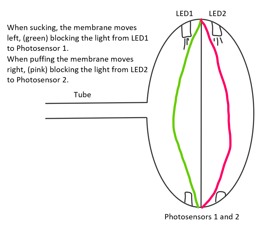
    For now, I had another idea: suspend an elastic flat membrane in a small cavity that has a tube attached to one side and may be somewhat (we'll see later) open on the other side.

    When puffed or sucked, the membrane would move one way or another and block the light between an LED and a photo-sensor on either side of the membrane.

    Said and done; I'll be back soon, with another cartoon build log.

  • Post-preliminary code testing

    Ana08/03/2018 at 01:13 0 comments

    No tube connected yet, but we're well on our way!

    All bugs mentioned in the previous post have been fixed, and you can see the code as of now here. I still have some commenting to do, but it's not the ugliest, and works good (so far!). 

    The problem with "36" printing instead of "#" (for non-existent characters) was easily solved by changing pMark's type from char to byte.

    The second problem (speed changing erratically) was caused by some code I forgot to remove. It was supposed to automatically detect the user's speed, however it wouldn't work for a dual-lever paddle.

    The third problem (random DIT's) was much more troublesome. I "debugged" (putting LOTS of print statements) the code and found out it lied in the switch/case statement. I tried to figure out the problem... I really did. In the end I just changed it into a series of IFs and ELSE IFs, hoped for the best, and tah dah! It works.

    I'll have to revisit the code later and attempt to pinpoint the problem, as I prefer to not leave things unsolved.

    Here is the morsing in action (The light labeled 'L' flashes morse code, and TX flashes when a character is sent):

    It's not the clearest video, but, I did what I could. Characters are printed to the serial port right after being morsed!

    -Ana

  • Preliminary Code Testing

    Ana08/03/2018 at 00:57 0 comments

    The programming is almost done (and VERY messy, I'm going to have to clean it up), and I've began testing with an Arduino Mega 2560.

    Some bugs I've noted:

    • 90% of the time, when you morse a character incorrectly, it will print "36".
    • After a few characters are sent, the morsing speed begins changing erratically.
    • Worst of all, every half a second or so, a "DIT"/"DOT" is sent without any action taken by the user.

    Hopefully, they are all minor problems. I believe the first problem lies here:

    void printPunctuation()
    {
      byte pMark = '#'; // Just in case nothing matches
      if (myNum == 71)
        pMark = ':';
      if (myNum == 76)
        pMark = ',';
      if (myNum == 84)
        pMark = '!';
      if (myNum == 94)
        pMark = '-';
      if (myNum == 101)
        pMark = '@';
      if (myNum == 106)
        pMark = '.';
      if (myNum == 115)
        pMark = '?';
      Serial.print(pMark);
    }

    The second and third issues are more of a mystery, and I need to make all the wait times for sending morse proportional, but we're getting there :)

    -Ana

  • Cat's Puff-Suck sensor log 1

    Cat08/03/2018 at 00:56 0 comments

    Our project is made of two main parts:

    - a puff-suck sensor that translates the puffing-and-sucking actions into electrical signals,

    - a micro-controller system (like an Arduino) that interprets the signals from the sensor into humanly readable text,commands or other information.

    On this occasion, my (Cat's) part is the sensor, and Ana does the programming

    I've been considering many ways to implement the mechanical part of the puff-suck sensor that would be suitable for Morse code input.

    I've known Morse code for a long time and it was easy to imagine puffing-and-sucking it, but a few requirements have to be met to make it efficient (I have no idea if the same requirements are suitable for "normal" puff-suck switches):

    - It has to have three states: puffed, sucked, neither

    - It has to be able to switch fast between the states

    - It has to work with relatively small volume of air

    - It has to be able to keep a state for a while (up to a few seconds if slow) without effort

    - Ideally it would provide some feedback

    Next time I'll write about some options I considered and some I discarded, at least to start with.

    Cat

View all 11 project logs

  • 1
    Electronics parts and schematics

    This project has two main electronic parts: one is an Arduino micro-controller board (pretty much any model will do) and the other one is an optical switch we control by puffing or sucking into a small cavity with a membrane at one end.

    For prototyping purposes we used an Arduino Mega 2560 just because it was handy.

    If we actually want to emulate a keyboard and a mouse we will likely use a small Arduino Leonardo variant.

    We've been wondering for a long time how we could make a switch that's easy to make and use without spending a lot.

    We think we got to a pretty good solution that has only one moving part, and some cheap electro-optical components.

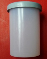
    The Film Canister
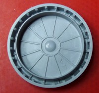
    The Cap (We use two of them)

    The electro-optical components are an IR (Infra-Red) LED (Light Emitting Diode) and an Opto-Transistor obtained from a cheap "QRD1114" Optical Detector.

    Normally the LED and Opto-Transistor are held by a shell and point in the same direction. If they are facing a nearby reflective surface and the LED is powered up, the IR "light" will be reflected onto the Opto-Transistor which will start to conduct.

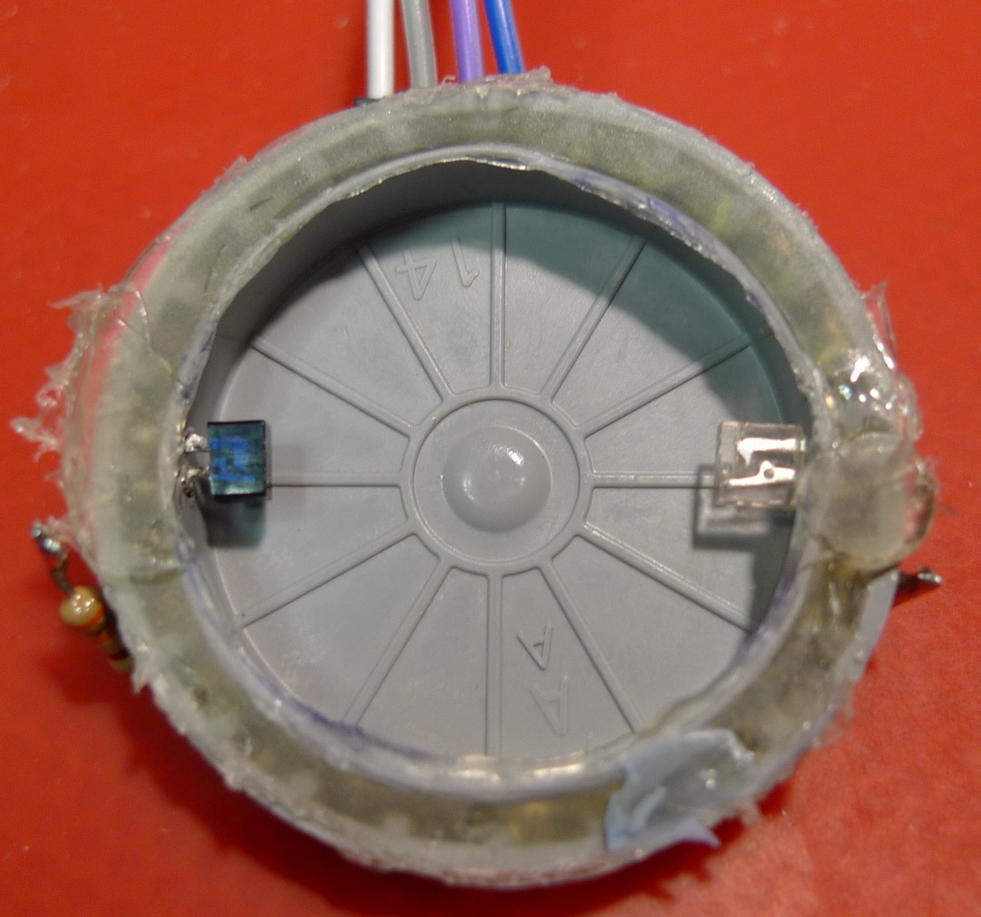
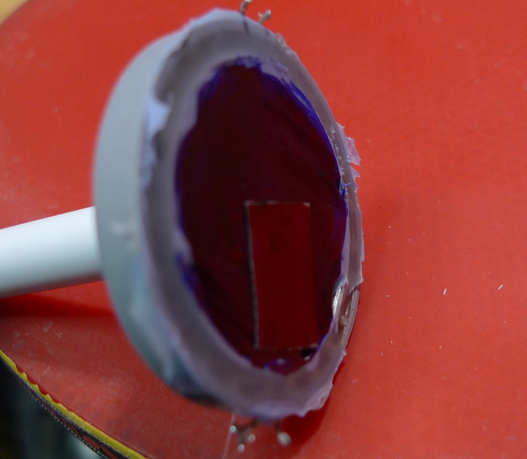
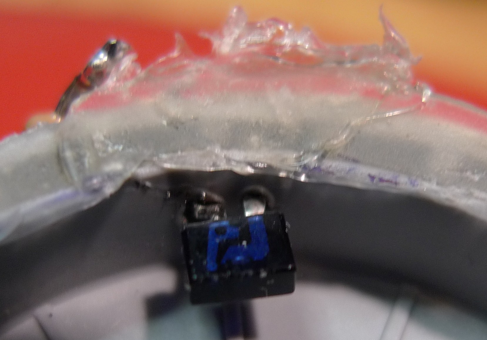
    In our case we removed them from the holding shell and we placed them on opposite sides of a film canister cap so that when the LED is powered up the IR "light" shines straight onto the Opto-Transistor, unless the membrane gets in the way.

    We place one pair on each side of the membrane so one is blocked when we puff and one when we suck.

    The moving part is a membrane cut from a rubber glove (could use a balloon) and is loosely glued onto a the open side of a film canister cap, but not before the LED and the Opto-Transistor are placed inside, pins pushed through the walls of the canister cap, while being heated with the soldering iron.

    One of the caps has a hole and a tube connected to it with hot-glue.  The tube is from a pen, but some arrangement that gets rid of saliva should be connected to it (this is a prototype for testing feasibility :-)

    This didn't work at first because the membrane wasn't opaque enough to the IR, but two pieces of duct tape fixed that (the black permanent pen we tried first wasn't enough).

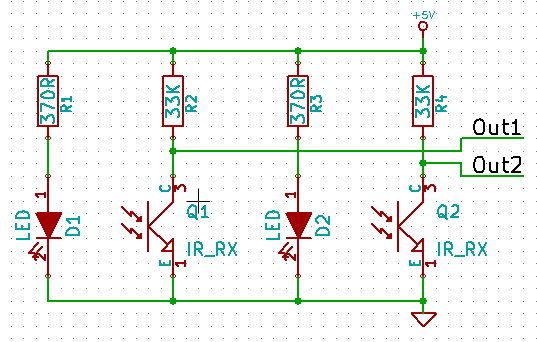
    The schematics for the switch also contain some resistors to get the right current through the LEDs (we chose just above 10mA) and pull-ups for the Opto-Transistors' collectors.

    Out1 and Out2 are normally Low because the IR "light" can get to the Opto-Transistors therefore keeping them "open" so they pull the outputs to ground.

    When we suck or puff through the tube, the membrane is pulled or pushed and blocks one or the other light paths therefore closing one of the Opto-Transistors so that output will go High.

    The outputs get connected to two digital inputs of the Arduino.

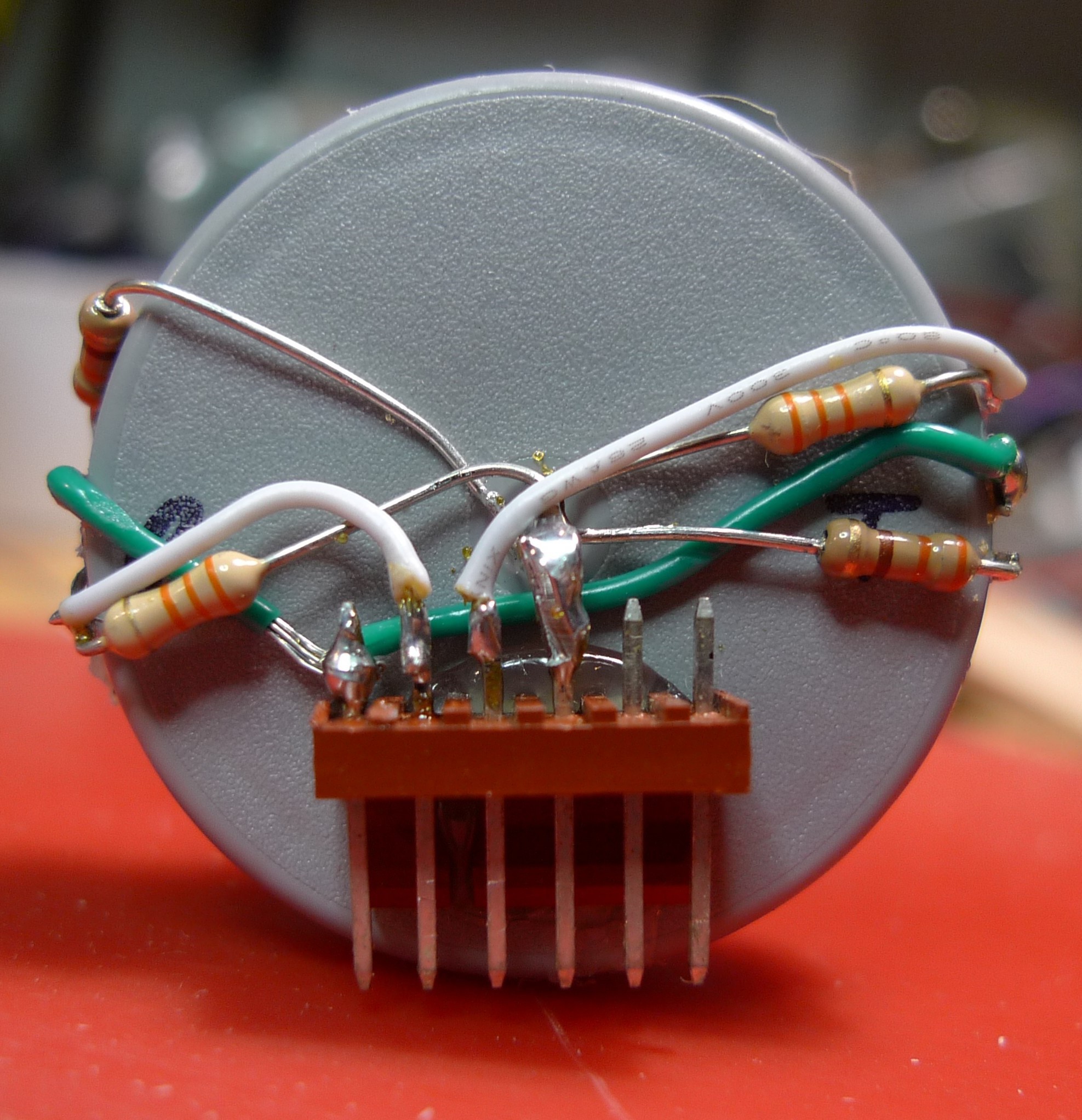
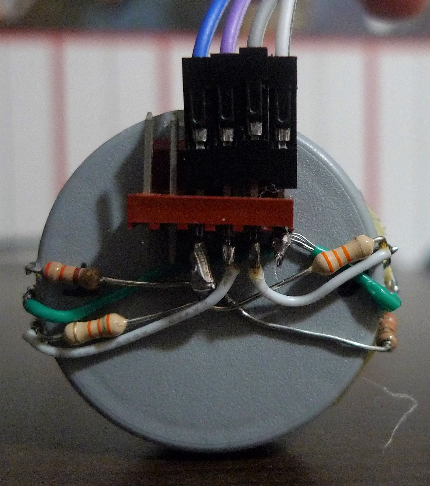
    Here you see a very ugly but functional implementation of the above schematics (with 330ohm resistors instead of the 370 shown in the schematics):

    Enough for today eh?

  • 2
    Get the Code

    You can get the code at our GitHub repo, and alter anything to your content.

    The method we used to translate Morse to text was taken from this website.

    For each character, we have a start bit (1) and add 0s for dashes and 1s for dots. Let's take Q for example.

    dash dash dot dash

    becomes

    10010, which when translated into base 10 becomes 18, which is why in our array

    char LetterSet[] = "##TEMNAIOGKDWRUS##QZYCXBJP#L#FVH09#8###7#####\\=61####+##2###3#45";

    the letter Q appears at index 18. Lower down in the code we also have some punctuation detection for numbers larger than 63.

    You may edit the code to your heart's content! Just remember to copy the licenses if you want to redistribute it :)

  • 3
    Connections

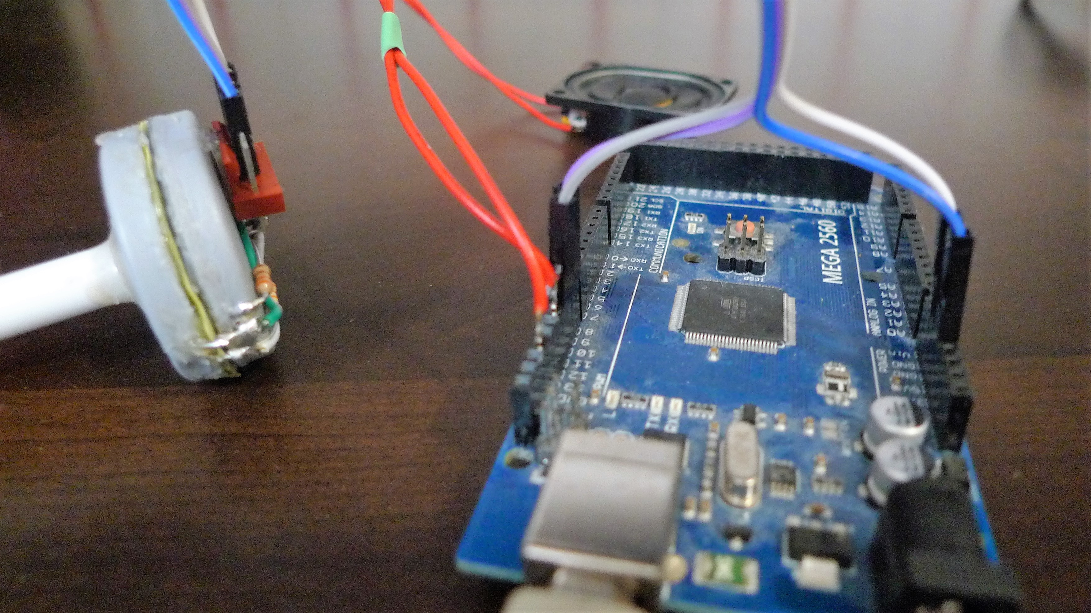
    Finally, it's time to connect the Puff-Suck tube to the Arduino. We're also connecting a speaker since it's pretty difficult to Morse without hearing the signal.

    This is our current (very rough, but working) setup:

    Here are the connections to the tube:

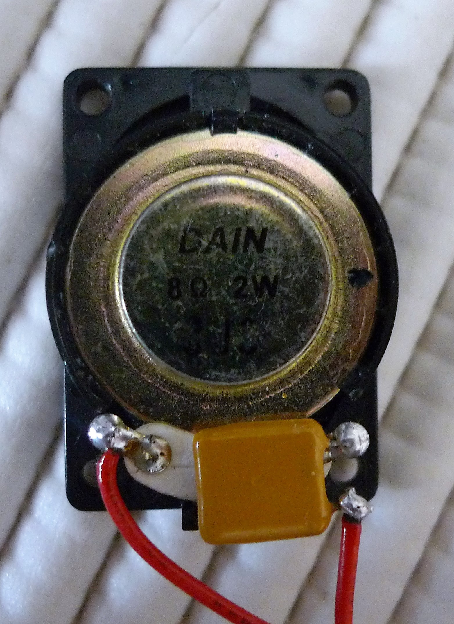
    Cat soldered a capacitor onto the speaker to prevent the speaker from getting the full 5 Volts and perhaps breaking..

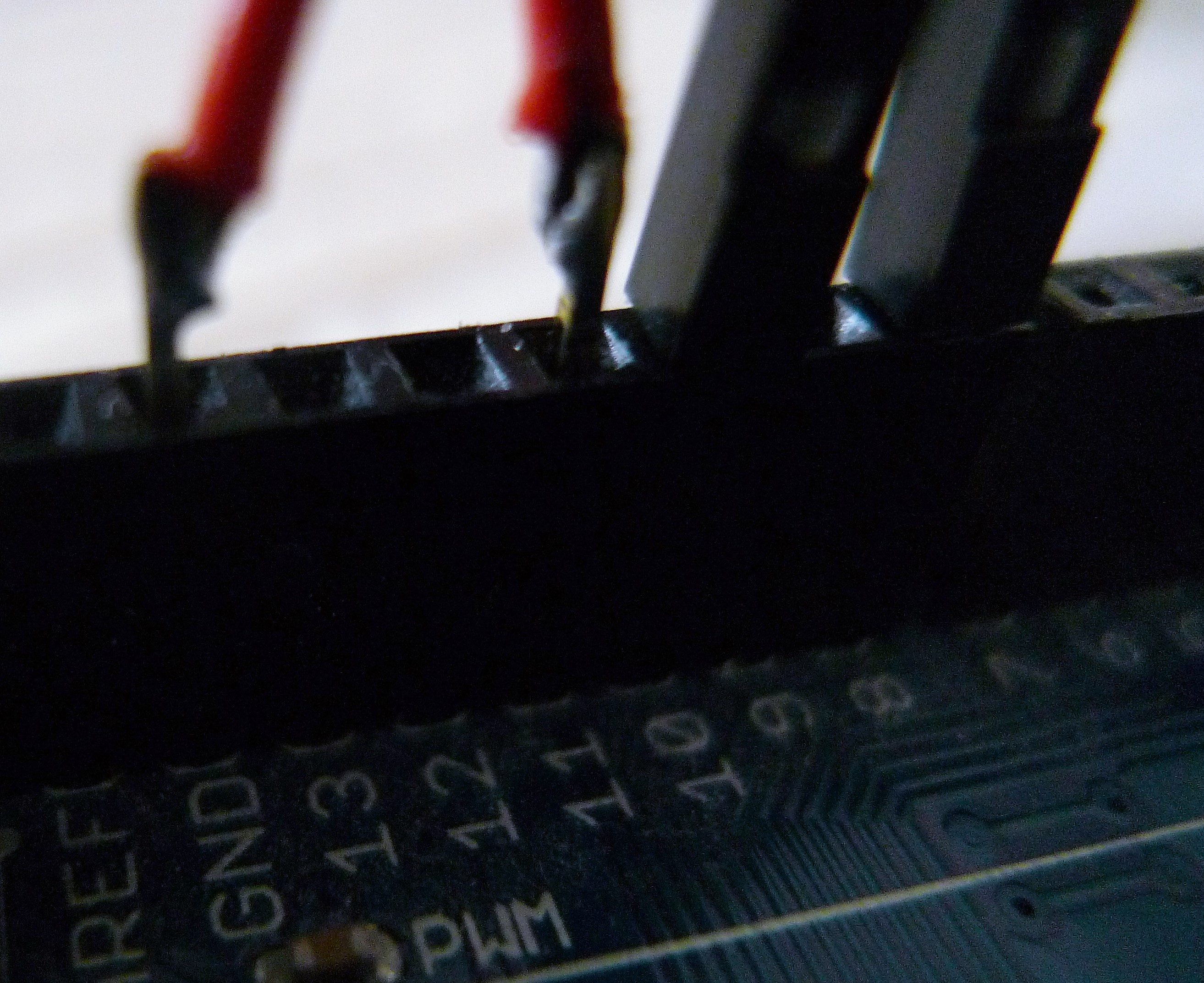
    The speaker is connected to pin 11 and ground on the Arduino, and the Opto-Transistor outputs (grey and purple wires) you saw in step 2 are connected to pins 8 and 10 (you can switch them to switch what each signals).

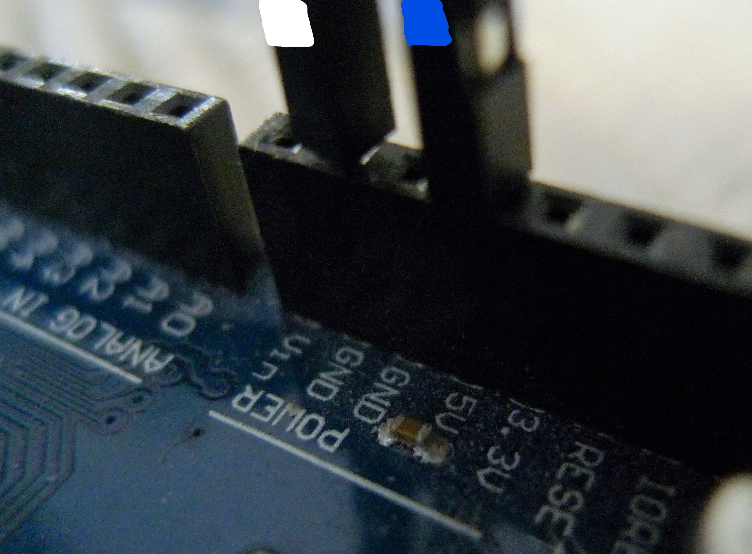
    And the power to the tube is provided by 5V (blue wire) and ground (white wire) on the Arduino:

    If you would like further detail on the instructions (or anything else for that matter), don't hesitate to ask in the discussion.

View all 3 instructions

Enjoy this project?

Share

Discussions

AVR wrote 08/23/2018 at 19:39 point

Great job, I dig the implementation!!

  Are you sure? yes | no

Ana wrote 08/23/2018 at 20:26 point

Thank you!

  Are you sure? yes | no

AVR wrote 08/24/2018 at 15:34 point

I really like the LED/opto transistor  implementation of the sensor its fairly clever. 

  Are you sure? yes | no

Gabriel wrote 08/05/2018 at 17:29 point

cool proyect... consider eliminating the LEDs and replacing the membrane with a piezo disk... output will be positive or negative depending on siping or puffing... this way you also get a "velocity" input.

  Are you sure? yes | no

Ana wrote 08/05/2018 at 19:41 point

Thanks! That was actually one of the things we considered, however a piezo disk only generates electricity while it's changing shape, so one would only be able to send a single dot/dash at a time.

  Are you sure? yes | no

Similar Projects

Does this project spark your interest?

Become a member to follow this project and never miss any updates